
naah
that was a joke , off course
I completely understand that - if you're novice to electronics , you're probably in sort of fear and frenzy what to do ;
so - general tip : take your time , don't rush and try to find necessary info before flipping the switch ....
here it is ( read first few pages of thread thoroughly ) :
http://www.diyaudio.com/forums/pass-labs/188691-illustrated-guide-building-f5.html#post2566447
fact that you need to short inputs was already stated somewhere where that procedure was originally written ........ if I remember correctly
Last edited:
Yes shorth the Imputs newbie myself but is there most definetley.
Just croccodile clips will do.
Newbie fear and frenzy that what it is
I realy tought that I was most definetley going even more bonkers while building mine.
You know I mean like:
Where is that screw driver I just put down and what the Fuz am I doing in the kitcen? did I want a cofee? nah Just had one
a raight where is the screw driver?
well newer mind it alwayse turn up I may be beter having a coffe while here?
LULA why did you put my screw driver in the ketle?
and so on
Last edited:
Oky dokey define Jump around
50mV not to bad
Do you have speaker protection?
Well worth it before she goes "I told you so"
J fets stuck together and case closed?
Little thermistors next to mosfets? (Glued to drain pins of mosfets on mine)
Silly PCB with double layers tracks crossing all over the place so loads of stray capacitance? And or gate resistors to far away from gates causing oscillation?
Poor filtering on supply?
Cold solder somewhere?
Solder paste residue somewhere?
Multy turn pot out of range difficoult to adjust or damaged?
Really wish I could help this is most strange as I got 2.5 mV on mine
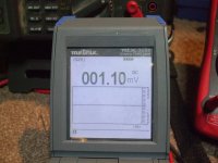
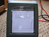
Picture 1 DC ofset while setting up and few hours later after quite a few traks
http://www.diyaudio.com/forums/swap-meet/182480-holco-mfr-15ppm-2w-sale.html
50mV not to bad
Do you have speaker protection?
Well worth it before she goes "I told you so"
J fets stuck together and case closed?
Little thermistors next to mosfets? (Glued to drain pins of mosfets on mine)
Silly PCB with double layers tracks crossing all over the place so loads of stray capacitance? And or gate resistors to far away from gates causing oscillation?
Poor filtering on supply?
Cold solder somewhere?
Solder paste residue somewhere?
Multy turn pot out of range difficoult to adjust or damaged?
Really wish I could help this is most strange as I got 2.5 mV on mine
Picture 1 DC ofset while setting up and few hours later after quite a few traks
http://www.diyaudio.com/forums/swap-meet/182480-holco-mfr-15ppm-2w-sale.html
Attachments
@mk57: This is not usually something to be worried about.
The F5 output offset is determined by the relative temperature differences between the output devices. The Thermistors are the feedback method by which the offset is kept under control.
When one transistor warms up it passes more current, warming up even more until the thermistor attached to it starts pulling the bias down. As it goes down it cools, the thermistor then starts allowing more bias, warming it up. Now go back to the beginning of this paragraph.
What you are seeing is the Yo-yo effect between the two transistors. I had this exact issue when I built mine, so I simply removed the thermistors altogether. True to Nelson's prediction the amp took a lot longer to warm up, but the offset stayed where it was.
The most unfortunate part of this arrangement is that in major variations of ambient temperature, the bias needs to be adjusted again as there is no bias feedback mechanism. I have no major problems with this, because in my country it is inconceivable to use such a hot amp during the summer. So I set it with winter bias, and leave it at that.
After listening to my F5 for a little while I tried to bias up to 0.8V. Yes it's definetly more dynamic, and more Prat as well.
But its Hot! I'm getting about 52C on the outside of the heatsinks. 62C at the top of the Mosfet case, and about 47C internal case temp. My transformer is reading about 55C
Previously at 0.6V bias I'm getting about 45C at the heatsink and 53C at the top of mosfet case.
Oh and I'm using a thermocouple to measure temp... I think that should be more accurate than the IR ones.
Note: I'm also using caddock MK132 as the 4 feedback resistors (not the big blue panny 3W ones)
Is this going to be ok?
Simple matter to calculate the internal temperature of the device by using the power dissipated (your bias and supply voltage determine this) and then using the device Tj-Tc specification.
IIRC there is about a 20 degree difference between what you measure at the case and the junction itself - which is fine till about 150C. So you're within the limits of the device.
However at higher temperatures the power handling of the device drops off quite rapidly. Check the temperature derating of the device to know whether you're within safe limits. Offhand, I think you are. Mine measured about 45 degrees on case surface with default bias. The output resistors got very hot even at the 0.6V setting, and almost burning to the touch (85 degrees) at 0.9V bias. Obviously, I never stayed at that bias level for long.
- Status
- This old topic is closed. If you want to reopen this topic, contact a moderator using the "Report Post" button.
- Home
- Amplifiers
- Pass Labs
- What determines how high bias can be on F-5?