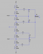
If I read the books wel, but also see the schematic of the K1 K1 crown amps who is in fact a BD modulator but she uses two buck converter outputs, who is by the way tricky, nice to see the resistor banks who prevent thermal runaway when she do overlap it.
I drawn the triangle generator and she do use there a adjust with a pot for overlap, in other papers she do use triangle with +vcc and -vcc and two opposite input audio signals who give then the two signals, a lot is unclear there.
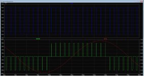
Do seem that I did get a low hd amp, no DB, did not work well, but some other form. See pics of output amp setup. -100dB distortion
regards
When you say two buck generators, do you mean self oscillating class D topology or class D topology with separate triangle generator. ?
This schematics seems to be self oscillating, but this resembles more like two bridge amplifiers, hmm? BD modulation , heach half bridge should see only half of total voltage I would say. Like +Vcc and 0 V for one and 0V and -Vcc for other.
Question is what is needed to convert one AC audio signal (sine signal) to two signal, one signal is only positive part (top of the sine) and other half is only negative half (bottom of the sine). Problem is that in self oscillating topology we dont have two triangles.
Probably class AB inverter should be used.. Topology from AB class amplifiers.. Something like that
Overlap is good because low frequency audio requires the most power, and thus class D might be most appealing. Also, crossover distortion for low frequency audio is potentially more subjectively bad because the lower frequency means the signal is in the crossover region longer.
But overlapping causes distortion also. Lowest distortion would be when triangles are matched perfectly in BD modulation ?!
has some done here, two triangles do work, can overlap then also for idle current.
Need to make two triangles not inverted, but needs negative and positive part.
Ive hobbie, learn a lot of it, because class d is quite new for me.
regards
Would not overlaping cause more distortion the same as if two trianges have some voltage gap between them.
Prevention of overlapping can be done to the nS range, the same as dead time control.
But still am am not sure if you are using right topology. I will draw just BD modulation output topology.
Overlap is good because low frequency audio requires the most power, and thus class D might be most appealing. Also, crossover distortion for low frequency audio is potentially more subjectively bad because the lower frequency means the signal is in the crossover region longer.
Oke, agree, but idea is that the triangle is used, then the overlap is the same al along, it is a high frequency bias, like a ab amp, it is sensitive, and maybe even runaway occur.
There are as I did see and read much different systems, and ideas, I do like the triangle version the most, because these are always the same if adjusted, when using audio offset yes, the lower frequencies are longer in the bias field..
regards
I should say I don't know because I'm not understanding it very well. My hunch leads me to recommend a standard modulation method based on my preference for about 95% or more of the system power going to low frequency reproduction in a system that has dedicated low frequency amplification, and separate higher frequency amplification. That is, my experience leaves me liking at least biamped systems rather that amplifiers handling full range. A benefit is that at least biamping should reduce intermodulation distortion, too.
Well, so, if a class D amp is just handling low frequency audio, which is were they are best, in my opinion, then it is best to try to be sure that there isn't any crossover distortion. The standard modulation method (including self-oscillating UcD) should have the advantage there because the output MOSFET totem pole square wave switches between +/- power supply voltages, bipassing the crossover region. (Written especially in response to Kees52 and Grizlek.)
Well, so, if a class D amp is just handling low frequency audio, which is were they are best, in my opinion, then it is best to try to be sure that there isn't any crossover distortion. The standard modulation method (including self-oscillating UcD) should have the advantage there because the output MOSFET totem pole square wave switches between +/- power supply voltages, bipassing the crossover region. (Written especially in response to Kees52 and Grizlek.)
Last edited:
When you say two buck generators, do you mean self oscillating class D topology or class D topology with separate triangle generator. ?
This schematics seems to be self oscillating, but this resembles more like two bridge amplifiers, hmm? BD modulation , heach half bridge should see only half of total voltage I would say. Like +Vcc and 0 V for one and 0V and -Vcc for other.
Question is what is needed to convert one AC audio signal (sine signal) to two signal, one signal is only positive part (top of the sine) and other half is only negative half (bottom of the sine). Problem is that in self oscillating topology we dont have two triangles.
Probably class AB inverter should be used.. Topology from AB class amplifiers.. Something like that
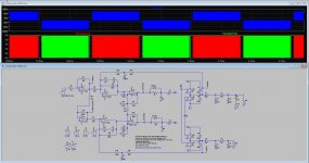
I all the papers I did see is bd modulation, and I think comparators do make that signals and the output just follow, I have also seen the signals needed for bd, and has just fase shifted comparator output interleaved, it is interleaved output in fact.
so need some more time to find out. it seems that two separate triangles inverted, one positive part other negatve part do work around zero there is then the overlap for bias in the coil to setup for zero crossover.
I did put in a triangle generator and the comparator signals are oke as with papers but no interleaved output, it did give very nice current, but strange voltages over speaker output.
In scond picture you see BD modulation with the self oscilating version, last picture you see low HD from a open loop triangle version, triangle circuit is very lineair version from crown amp where it has a offset pot for the bias adjust, (overlap) there the power output just use plus and minus voltages, as with all the orther inclusief picture 2 version and you see clear bd.
regards
Attachments
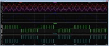
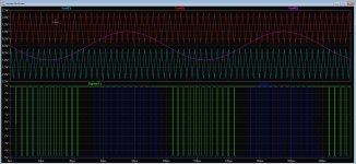
Here schematic and signals from comparators and output, clear see signal opposite from zero voltages, even with diff supply on output section, comparators do decide how it does. in picture two you see the output sinusoidal with uge crossover signals, these because it is self oscillation and as such it is maybe difficult to include the bias adjust section, maybe on the + inputs of comparators or inject small pulses making it a bi-bd version.
I have separate the section, and still I get uge shoot throughs, and as you see crossover, I did try to overlap, however with a self oscillating version, I do not now how, did try some offsets on the comparator and such, maybi opposite offsets needed, otherwise BI-uniform bd.
Pic one I have separate the two halves, on the output, still get 7 K-amp shoot through.
Attachments
Have you tried adjusting the control settings on the switches
If i try to overlap things get out of offset, I do not now if a self osc type do work, most we need small pulses injected in tho zero zones to get a bias in the coil so crossover dissapair.
normally dead time is not needed here, so the high current I see is strange, maybe grizlek who made the sim switches and such can answer, maybe diode problem, freewheel current..
regards
It is a good thing to be careful to avoid crossover distortion.
I wasn't able to read the voltage settings on the switches because of blur. I think they should turn on and off at least a few volts above ground. From my impression of the circuit, having control voltages in at least a moderately positive zone is necessary to prevent them being biased on all the time.
I wasn't able to read the voltage settings on the switches because of blur. I think they should turn on and off at least a few volts above ground. From my impression of the circuit, having control voltages in at least a moderately positive zone is necessary to prevent them being biased on all the time.
Last edited:
It is a good thing to be careful to avoid crossover distortion.
I wasn't able to read the voltage settings on the switches because of blur. I think they should turn on and off at least a few volts above ground. From my impression of the circuit, having them need control voltages in at least a moderately positive zone is necessary to prevent them being biased on all the time.
If you have ltspice, I presume you have I send the .asc.
regards
Attachments
To get a reasonable current output with low HD, it give a very strange voltage who is quite high and make no sense.
maybe models in ltspice, or ltspice can not simulate it well, or i do wrong, but read books about it and i do nothing wrong in fact, models of comparators can be reason.
I need to read more about it, strange.
This pics it do work but much rare voltages on output.
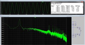
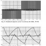
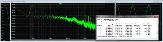
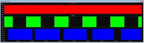
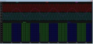
Pic 1 = you see it does double the carrier frequency, I put in 250 Khz and it doubles.
Pic 2 = for a open loop it has quite low distortion on 12 amps output.
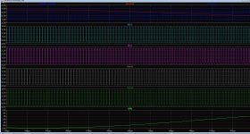
Pic 3 = all signals, I do not see the alternating signals on the bridges, strange.
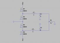
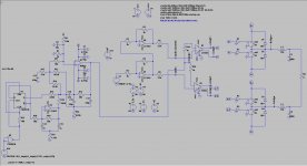
Pic 4 = schematic. I have the triangle generator taken from crown as test.
regards
maybe models in ltspice, or ltspice can not simulate it well, or i do wrong, but read books about it and i do nothing wrong in fact, models of comparators can be reason.
I need to read more about it, strange.
This pics it do work but much rare voltages on output.
Pic 1 = you see it does double the carrier frequency, I put in 250 Khz and it doubles.
Pic 2 = for a open loop it has quite low distortion on 12 amps output.
Pic 3 = all signals, I do not see the alternating signals on the bridges, strange.
Pic 4 = schematic. I have the triangle generator taken from crown as test.
regards
Attachments
Last edited:
I inverted the Vswitch drive signals.
Thanks
I already try that, still get strange outcomes, not switching from null to plus and min voltages but go to supply lines.
You did remove some parts from comparators, that are hysteric parts, needed to make the comparators schmitttriggers.
Last picture was from your changed version with schmitt triggers. still switching between rails, and little strange output
comparators. the first picture is a triangle version with also rail to rail switching, but do double the carrier and suppress
the original carrier frequency, what means it work, but in sim it is not clear.
regards
Attachments
Last edited:
You're welcome. With the hysteresis components, I observed crossover distortion. Unfortunately, you had already tried it and observed that other problems were still in the circuit.
My adding the inverters apparently removed a problem of offset intrinsic with the op amp. That was my thought about it. If I get a chance, I might take a further look at the circuit.
My adding the inverters apparently removed a problem of offset intrinsic with the op amp. That was my thought about it. If I get a chance, I might take a further look at the circuit.
Last edited:
I inverted the Vswitch drive signals.
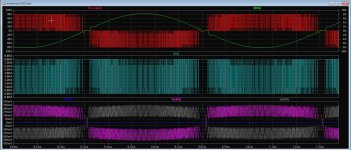
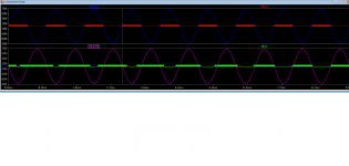
I see crossover distortion here...
Also why a+ corresponds with one sine, and a- does not correspond with other sine?
Attachments
Last edited:
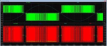
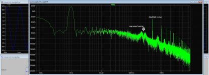
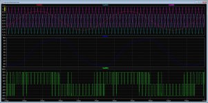
Ok I figured out why. on the schematics RC snubber is JUST ON ONE side, and missing on the other side. This was causing imbalance.
Adding snubber to other side, reduces THD 5 times, and now is only 0,05 %.
Also adding snubber to both sides, crossover distortion is not visible any more !
Adding snubber to other side, reduces THD 5 times, and now is only 0,05 %.
Also adding snubber to both sides, crossover distortion is not visible any more !
Attachments
Did you swap the input signals to the Vswitches when the inverters were in the circuit?
Hi
I did simulate as it was, after editing by you. I did discover that removing the two caps from the hysteric network gives overlap so the crossover is much less, what you did, to ground and no hysteric did leave a very small amound of crossover left.
I had that thought also with the hysteric components, that was why I did think about very small pulses what need to be injected and as such adjust bias. Or overlap as in pics.
Very strange that the book says it needs to be done this way and in the simulation it does not, for example the output waveform from your edited version is not as it suppose to be, but swings between the supply rails, in the school book is not mention about about supplys who are separated plus and minus versions. the way it do work is just let the comparators switch the right way, only possible by inverter triangles and one audio signal or vice versa a single triangle just on zero signal and double audio signals like in pictures.
Last pic uge current, that is not possible with the given output signals going from zo to plus, and minus rails, maybe @grizlek it is in the models? setup pf switches or diodes? freewheeling current?.
In pics I did try to explane the way of hoe comparators are driven, but the books did say otherwise, like triangle is symetrical, and did not work and I have only positive swing triange with two opposite audio signals, or two triangles in opposite signal with just one audio signal, movind offset do close or open the gap in output stage.
regards
Attachments
-
 ScreenHunter_974 Mar. 17 17.54.jpg253 KB · Views: 53
 -
 ScreenHunter_973 Mar. 17 17.36.jpg403.8 KB · Views: 47
 -
 ScreenHunter_972 Mar. 17 17.27.jpg371.9 KB · Views: 50
 -
 ScreenHunter_969 Mar. 17 17.17.jpg438.5 KB · Views: 59
 -
 ScreenHunter_968 Mar. 17 17.15.jpg357.4 KB · Views: 63
 -
new-test-threelevel.zip2 KB · Views: 48
Last edited:
- Home
- Amplifiers
- Class D
- What Class-D amp give best sound?