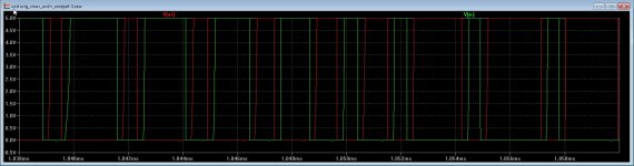
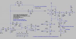
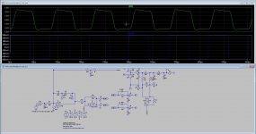
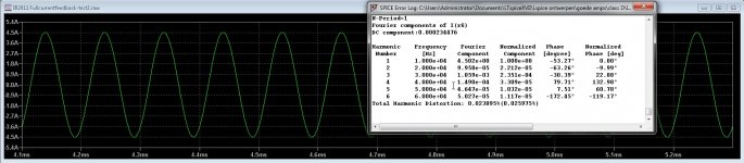
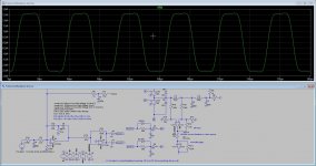
Same schematic now with excessive dead time, deadtime generator capacitors are 1 nF.
Question, I need a dead time generator for the IR 2110 what is the best way, a nand port, or buffers with schmitt triggers, (output buffer schmitt trigger and input normal buffer).
inverting is not needed, just switch the signals do also.
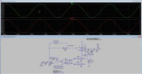
For the current feedback, there is very much fase shifting, so much that when on 1 Khz is oke and promissing but on 20 Khz the fase shift is so much that the feedback get lost and the input opamp get clipping including the current opamp.
So the current feedback has work on it, to find out how it work best so I go read some papers about motor inverters who use capacitor feedback, it is a very nice idea to get good measurepoint there, it is a very precise feedback point, the low pass however is a bad fase shifter, maybe a bessel lowpas 24dB octave can be used these have liniair fase shifting, a Rc bessel allpass filter can correct the feedback.
Question, I need a dead time generator for the IR 2110 what is the best way, a nand port, or buffers with schmitt triggers, (output buffer schmitt trigger and input normal buffer).
inverting is not needed, just switch the signals do also.
For the current feedback, there is very much fase shifting, so much that when on 1 Khz is oke and promissing but on 20 Khz the fase shift is so much that the feedback get lost and the input opamp get clipping including the current opamp.
So the current feedback has work on it, to find out how it work best so I go read some papers about motor inverters who use capacitor feedback, it is a very nice idea to get good measurepoint there, it is a very precise feedback point, the low pass however is a bad fase shifter, maybe a bessel lowpas 24dB octave can be used these have liniair fase shifting, a Rc bessel allpass filter can correct the feedback.
Attachments
Last edited:
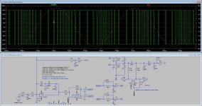
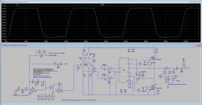
Some updates with current sensing feedback.
As fior now I did let it work from 20 to 20Khz or higher when low pass is higher.
I have disconnect the voltage feedback completely but can be reconnected and tuned for double feedback.
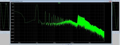
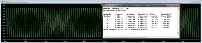
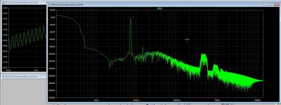
Last two pictures you see distortion, one low one high with only oneven harmonics. These are because of the diff current feedback common mode error, we need a good opamp with very high bandwidth, a video current feedback type do well, I have also did a schmitt trigger before the feedback, but if these are of help I do not now, I do now, it go from 20 to 20Khz without a problem.
Seems that fase shift do also get quite in line, making voltage feedback work better when use it together with current feedback.
regards
regards
As fior now I did let it work from 20 to 20Khz or higher when low pass is higher.
I have disconnect the voltage feedback completely but can be reconnected and tuned for double feedback.
Last two pictures you see distortion, one low one high with only oneven harmonics. These are because of the diff current feedback common mode error, we need a good opamp with very high bandwidth, a video current feedback type do well, I have also did a schmitt trigger before the feedback, but if these are of help I do not now, I do now, it go from 20 to 20Khz without a problem.
Seems that fase shift do also get quite in line, making voltage feedback work better when use it together with current feedback.
regards
regards
Attachments
-
 ScreenHunter_798 Feb. 08 14.04.jpg237.7 KB · Views: 65
 -
 ScreenHunter_802 Feb. 08 14.34.jpg243.1 KB · Views: 100
 -
 ScreenHunter_801 Feb. 08 14.17.jpg173.1 KB · Views: 102
 -
 ScreenHunter_805 Feb. 09 13.47.jpg278.9 KB · Views: 61
 -
 ScreenHunter_799 Feb. 08 14.13.jpg118.3 KB · Views: 49
 -
 ScreenHunter_796 Feb. 08 13.40.jpg126.5 KB · Views: 570
 -
 ScreenHunter_795 Feb. 08 13.27.jpg230.5 KB · Views: 581
 -
 ScreenHunter_792 Feb. 08 13.22.jpg255.8 KB · Views: 596
Last edited:
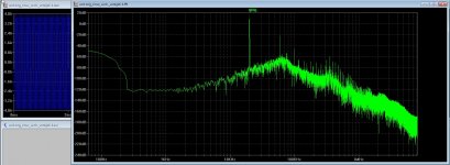
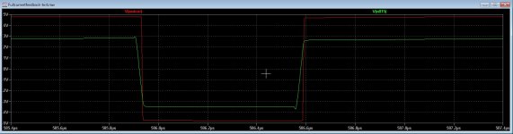
Open circuit and square, it looks like the coil get nicely into the loop, because the overshoot is sompletely gone, with a voltage feedback I get overshoot without extra measures.
So this looks like it works, and I have here complete coil current feedback, and no capacitor.
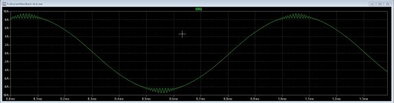
The distortions you see is with highest HD double feedback, current and voltage, the lowest HD is with only current coil feedback, last picture is without load, then output voltage shoots up, and down but not big currents in output stage.
regards
So this looks like it works, and I have here complete coil current feedback, and no capacitor.
The distortions you see is with highest HD double feedback, current and voltage, the lowest HD is with only current coil feedback, last picture is without load, then output voltage shoots up, and down but not big currents in output stage.
regards
Attachments
Last edited:
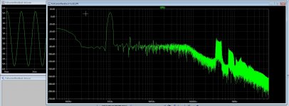
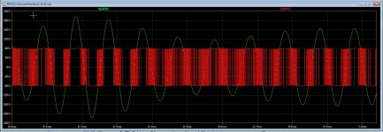
IMD test, I do not now if this can be simulated, I have put two voltage sources, one 60 hz and one 7 Khz, 60 hz 1/4 output of 7 Khz, as I did read.
if it is oke, then IMD is also very low. But only if this will work, maybe I think it is low because of this way it can not be measured.
if it is oke, then IMD is also very low. But only if this will work, maybe I think it is low because of this way it can not be measured.
Attachments
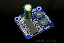
Excuse me for interrupting, but I was wondering if TPA32xx is a solid competitor and how does it compare with the list mentioned on the first page of this thread.
I´m also interested how can TPA 32 compare with others
Go with TPA TI amps. I think they sound wonderful! They are dirt cheap too. Nothing to lose here. I cannot wait to have the new TPA3255 which is little bit more expensive but not much.
Surprised there's only one mention of the TPA325X amps in a thread about best class D - the TI EVMs are definitely the best class D amps I've heard - beats TK2050, TA2020 and TPA3116. I've not listened to the Hypex UcD though.
If we all go buy ready made electronics then this forum stop to excist, included the fun, it is just the challence to experiment and build electronics and learn.
For as quality the tube mosfet hybrids do still sound the best, I have not yet build the class d, but maybe a open loop with air coil and oil capacitor and see what happens. Need to make a lineair as possible sawtooth, maybe digital programmed.
regards'
For as quality the tube mosfet hybrids do still sound the best, I have not yet build the class d, but maybe a open loop with air coil and oil capacitor and see what happens. Need to make a lineair as possible sawtooth, maybe digital programmed.
regards'
Last edited:
The Nerd Gene will always survive!
The Nerd Gene will always survive! There will always be a place for tinkers to gather and share ideas.
You may find the Class D development conducted by Captain Sensible of some interest.
See: DIY Class-d amplifier based on SODA, using HIP4080A

If we all go buy ready made electronics then this forum stop to exist.
The Nerd Gene will always survive! There will always be a place for tinkers to gather and share ideas.
You may find the Class D development conducted by Captain Sensible of some interest.
See: DIY Class-d amplifier based on SODA, using HIP4080A
If we all go buy ready made electronics then this forum stop to excist, included the fun, it is just the challence to experiment and build electronics and learn.
I buy a whole lot of ready made electronics. Starting with a board and then modding the hell out of it is the best way to learn how to design for oneself that I've found. So my motto has become 'never leave it stock!'.
On TPA3255 I've been playing with the cheapest ready made board (258rmb on Taobao so around $40) and in stock form it was OK to good but nothing special. Modded though (attention going to power supplies firstly) its about the equal of an equally heavily modified TDA8932 board - but has greater power capability. Which is really, really good. I'll explore whether the (considerably more expensive, even with discount) TI EVM has employed some circuit tricks which have been left off this board.
my motto has become 'never leave it stock!'.
Amen to that! If I know it can be upgraded, its impossible to resist trying, including TI EVMs.
")
Some updates with current sensing feedback. <snip>
I wonder would it work with single LC filter, I mean without additional filter outside feedback loop . Any filter outside loop means higher output resistance and other problems of element without feedback.
So would it work just to increase first filter L and C values to right values?.
Unfortunately lately I am busy with something completely different, I am simulating stages of tube (valve) guitar amplifier, LOL
If we all go buy ready made electronics then this forum stop to excist, included the fun, it is just the challence to experiment and build electronics and learn.
For as quality the tube mosfet hybrids do still sound the best, I have not yet build the class d, but maybe a open loop with air coil and oil capacitor and see what happens. Need to make a lineair as possible sawtooth, maybe digital programmed.
regards'
Tube mosfet? Can you link schematics? I would says this included "good" harmonics if we have tube and not complete linearity...
Having simple class D with tubes would be "super geeky" hehehe
... its about the equal of an equally heavily modified TDA8932 board - but has greater power capability. Which is really, really good.
This?
An externally hosted image should be here but it was not working when we last tested it.
or this?
An externally hosted image should be here but it was not working when we last tested it.
What did you do them? I guess a pair of mono, one slave the other master, set to its max frequency and a funky filter? Please share if you don't mind.
I wonder would it work with single LC filter, I mean without additional filter outside feedback loop . Any filter outside loop means higher output resistance and other problems of element without feedback.
So would it work just to increase first filter L and C values to right values?.
Unfortunately lately I am busy with something completely different, I am simulating stages of tube (valve) guitar amplifier, LOL
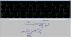
The feedback has still the coil inside, but is current feedback with a current feedback video opamp, did see it works because there was no overshoot, combine this with voltage feedback and tune.
I do now people buy ready made amps and mod them, good thing and it have also a pcb who works, I do prefer made it myself, incl pcb.
The last versions I go made a pcb for, just think what dead time generator I use, nand, inv buffer, schmitt trigger etc.
two squares 20khz, one voltage and last coil current diff feedback. You see the current version controls the coil very good.
regards
Attachments
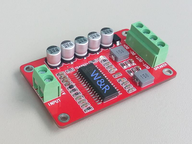
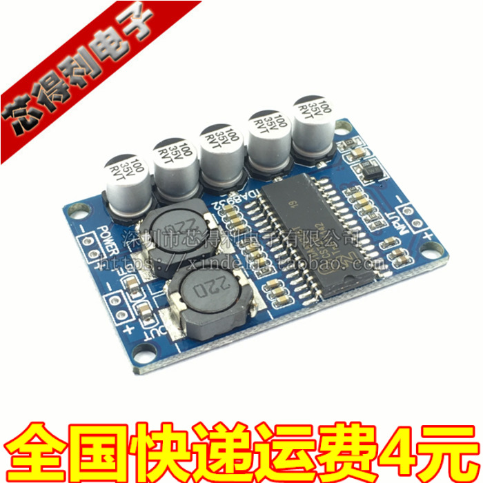
It was one of these, which right now I can't find on Taobao. When I first discovered it they'd scratched off the markings so that no-one would know it was a TDA8932 and it turned up on Taobao when I happened to be searching for TDA2030. This pic I have on my blog. Nowadays they don't bother to scratch off the ID, around the same time they lowered the price but it was still a bit more expensive than the ones you're showing.
The mods didn't change the switching frequency rather they addressed decoupling on the analog supply rail (pin 8). The DS doesn't put enough capacitance there, with only an RC from the main supply. It needs its own regulator and a couple of thousand uF then it comes into its own. I also ran it via a 2:1 step down trafo into my speakers, this improves bass intelligibility. Oh and input transformers (SE -> bal) too which I wound myself on 19mm EP cores.
The mods didn't change the switching frequency rather they addressed decoupling on the analog supply rail (pin 8). The DS doesn't put enough capacitance there, with only an RC from the main supply. It needs its own regulator and a couple of thousand uF then it comes into its own. I also ran it via a 2:1 step down trafo into my speakers, this improves bass intelligibility. Oh and input transformers (SE -> bal) too which I wound myself on 19mm EP cores.
Attachments
It was one of these, <snip>
Thanks - need a small footprint low power amp and I don't particularly enjoy TPA3118 etc so this looks like it's worth a try. And have a Happy Year of the Woofer!
Ha, good one, you too I too wasn't highly impressed with TPA3116 which was what led me to TDA8932 - Cheap TPA3118D2 boards, modding them and everything that comes with it
I too wasn't highly impressed with TPA3116 which was what led me to TDA8932 - Cheap TPA3118D2 boards, modding them and everything that comes with itThe feedback has still the coil inside, <snip>
But between feedback and speaker there is additional LC filter? Why not combining those two filters into single filter?
- Home
- Amplifiers
- Class D
- What Class-D amp give best sound?