I am planning on building a 3 or 4 way LM3886 amp to use with a miniDSP to drive some OB speakers I am building. However in the meantime until I get parts ordered for that I'm thinking why not use parts I have on hand to build a simple discrete transistor OPS, 3 or 4 way amp with op amp active crossover.
I have the following parts on hand:
About seven LM324 quad op amps
Eleven TIP31 40V power transistors and individual heat sinks for each (no giant heatsinks sadly, although I have a PC CPU watercooler I could use if I had a heat spreader and mica insulators)
Assortment kit of 2 each of 75 different values of 10W ceramic power resistors
Two 24V 10A switching power supplies that could be series connected to get +24V/-24V
Lots of P and N channel switching power mosfets (from a motor PWM project, would produce terrible audio I'm afraid)
Resistors, capacitors, wire, boards etc.
I'm leaning towards a class A amp because I have an excess of power resistors; unfortunately the heat sinks will limit me to only a few watts per transistor. Is there a way to make the resistors take more of the load? I got all excited about a "bridged class A" idea I had which would drive the speaker differentially and let both outputs float independent of ground at idle, until I realized that analyzing the current paths through each quadrant and applying the theorem that any series circuit is equivalent to the same elements rearranged allowed me to transform the bridged class A into a class AB with redundant power resistors grafted on!
Just thinking out loud here- this is what Macgyver would do: Since all same sex outputs - make a single ended class A driven by opamp. Use one of TIP31 as constant current source through several emitter resistors. Have the opamp drive the lower TIP31 that is pulling on the CCS. Have a big 3300uF cap AC couple the output between the emitter and source resistors. Use one of the opamps provide the bias current and self-feedback regulated via sensing the current through the emmitter resistor.
Nuttin wrong with MOSFETs
Whatsa matta you don't like mosfets? You could build a little Class D amp with the Mosfets. I'll attach a schematic.
This can be bridged to double power by replicating the output section and driving the second section from opposite phases from the CMOS gates.
Whatsa matta you don't like mosfets? You could build a little Class D amp with the Mosfets. I'll attach a schematic.
This can be bridged to double power by replicating the output section and driving the second section from opposite phases from the CMOS gates.
Last edited:
Or I could use the MOSFETs to build a switch mode constant current top end to drive a TIP31 bottom end... Using only parts from my junk box is good, using ALL the parts from my junk box would be fantastic!
If all you've got is a hammer, every problem looks like a nail, eh? 😉
LM324 (quad relative of LM358) is a terrible opamp for audio by any standard. You'll need to give it some healthy Class A biasing to get rid of the awful crossover distortion (think 5-10 mA a pop). Paralleling all 4 parts of one package might get voltage noise into not that much worse than TL07x territory (I've seen e_n values of 32, 40 or 48 nV/sqrt(Hz) depending on manufacturer, and quadrupling up would halve it). Then, however, its slew rate still is pretty slugtastic (0.5 V/µs tops) - that might be OK for a headphone out, but certainly not for a speaker power amp unless adding some extra gain behind it. You'd have to regulate its voltages down anyway, as it's not good for more than +/-16 V (but then again, parts choices are rapidly thinning anyway when exceeding 18 V per rail).
Coming up with a contraption that's not entirely terrible is probably doable, but it won't be easy at all with just these parts at hand (not even some small-fry transistors). It might still make a half-decent headphone amp with a single-ended emitter follower buffer including CCS.
Build a little Class D amp with the Mosfets. I'll attach a schematic.
This can be bridged to double power by replicating the output section and driving the second section from opposite phases from the CMOS gates.
finally posted schematic. The Op Amp sucks for audio, but here it is a comparator. LM311 would be better, but you said LM324. Mature technology for sure. The transistors can be whatever you have, small signal, and any pair of N channels. I tried hard to use a power resistor, put it in the Zobel network on the output. This would probably sound good if you build it on a PC board with power and ground planes galore, but like any switcher would be hopeless on a wired breadboard setup.
Attachments

Last edited:
Thanks for posting the class D schematic! Very nice. To be honest though I've done switching/digital stuff for a few years so I just thought it would be neat to try analog for a change. I'm not opposed to including switching elements, too, with this project (for instance I'm not insisting the power supply be a toroid transformer) but I am curious to see how far I can go with linear mode parts. Plus, I've been hanging onto some of these TIP31s for 20 years waiting for a use for them. 😀
Regarding the power supply range: the supplies do have a trimpot to set the voltage. I don't know what range they allow, however. I could of course just use a different supply or build a virtual ground for one 24V supply.
No Class D, OK, here's an attempt to use your Mosfets linearly
Mosfets do well in linear applications. Most people have seen the old IR app note that featured them, years ago.
http://www.infineon.com/dgdl/an-948.pdf?fileId=5546d462533600a40153559ed34311b1
Here is something for higher power.
Mosfets do well in linear applications. Most people have seen the old IR app note that featured them, years ago.
http://www.infineon.com/dgdl/an-948.pdf?fileId=5546d462533600a40153559ed34311b1
Here is something for higher power.
Attachments

Back to the top of the list. The Kurozz first amp uses TIP31/32 output transistors and a 20 V single supply.
http://www.diyaudio.com/forums/solid-state/297453-tips-first-amp-design.html
Look at version 2 or 3 in the thread, after the suggestions are taken.
Dead switcher supplies or TV's often have TO92 transistors in them which can substitute for BC546 566 etcetera. Not ideal sounding at 10 khz above but the price is right.
I build point to point, all you need is bare insulating board and some wire. See the last post of this http://www.diyaudio.com/forums/solid-state/236256-retro-amp-50w-single-supply-20.html for a picture of the board I am listening to now. You could kit bash the AX6 with resistor values from kurozz first amp to get a quasi comp output (no TIP32 required) and still use 20-24 v power supply.
Sorry for the replies that didn't address all of the comments - I was on mobile.
I have got some small signal transistors; sorry I didn't list them. Consider them under the "& etc." category. Just a couple 3904's and a couple 3906's. Somewhere I have a bunch of 2N2222 equivalents.
Since I'm building this in order to use separate amps for the high/mid/low, I could use different circuits depending on the frequency range. For instance, I found an LM1877; I could use that as a transistor base driver on the high frequency section. Although it is itself an outdated chip, it has 4x the slew rate and much more drive current than the LM324.
I hadn't considered that the LM324 may itself also need some bias current and/or have a dead zone. I wonder what the source(s) are of its noise? Perhaps I could run +/- differential signaling internally throughout the amp circuit, to at least reject common-mode noise. That would also allow me to set the absolute voltage to anywhere the op amps are most linear/least noisy (until I need to drive the transistor bases, that is!)
Finally, I'm not opposed to adding a fast microcontroller with a fast ADC to monitor the signal and apply correction inputs based on a calibration table indexed by voltage and vd/t. 😉 Sort of like miniDSP room correction but correcting problems inside of the amp. 😀
Well, walk before you run. DSP is an add on, do that later.
LM324 is **** for audio. You can do better with your pn2222 and pn3904's. The lowest op amp I'd go for audio is 4558, and that hisses if gain is high.
If you don't like AX6, this is pretty simple from bilb. It is quasi comp, no TIP32 needed. replace the 2n3055 with TIP31, turn rail voltage down to 20-24. Your pn2222 and pn3904 are suitable for that voltage, not a lot more. If the TIP31 don't have a C suffix, limit them to under 40 v rail, too. The transistor with the adjustment pot, that is mounted on the output heat sink to decrease bias current when the outputs heat up. Use insulators and heat sink compound on the output transistors and that one. As you see in my AX6 post, I use heat sinks on the drivers and VAS transistor too. Cut & drilled out of scrap window frame, they are free.
You'll notice I'm posting single supply amps schematics for newbies. that is because if one solder joint pops, a split supply amp, however good sounding, can toast your speaker with DC. That 1500 uf or 4700 uf capacitor between the amp & speaker is the greatest $3 protection device made.
With a bit of insulating board and some wire, you could build this in a couple of evenings. I use a yankee hand crank drill & #46 bit to drill the holes, and a #28 the holes for the #6 mounting screws.
Attachments

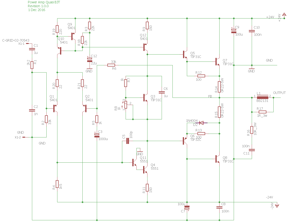
Cheap Quasi with TIP31s
Cheap Quasi with TIP31s
Cheap Quasi with TIP31s
Attachments

Last edited:
One question on the cheap quasi with TIP31's, which of the transistors (e.g. Q5?) can I actually use TO-92 case transistors for? I have to build between 2 and 4 stereo pairs if I want to have an amp per driver, so I want to make sure I distribute my power transistors well.
Nice design Slowhands! How does it sim? You have a PNP TIP32 in there though 🙂

Your hands ain't slow at all. 😀
Your hands ain't slow at all. 😀
Use TIP31 for the VAS, the second transistor bc286 in bilbo of sydney's design. I use a salvage heat sink, many don't. The input can be pn2222 or pn3904. The heat sensor transistor can be TO92 if you use enough heat sink goop and clamp it to the heat sink with a tie wrap. Metal can 2n2222 were used a lot in the early seventies for heat sensor transistors (Vbe multiplier they call it).
Everybody uses a PNP lower driver. If you've got some old TO5 can PNPs like 2n3906, or metal can TO39, you could put heat sinks on those, one dynaco PC15 is still working with TO5. Else just keep the rail voltage and volume low and use TO92 everything but the outputs.
There are some of those 1 watt tall TO92 in PCAT power supplies, look for a number starting with A. I've got five of those dead, they are about $20 new these days. 0.6 watt TO92's are .210" tall, the one watt ones are .240" or higher.
Starting low and cheap, masonite board is used by painters still, should be available from art supplies. If you want some real sixteenth thick Nema CE laminate like I use of easy to drill cotton, https://www.mcmaster.com/#8474K102 is >$10 for 12"x24". On the same order your can get some #4 screws for attaching heat sinks, some elastic stop nuts, for about $4 a pack of 50. Mcmaster charges me $8 freight minimum from Cleveland. Get the #46 and #28 drills for the holes on the same order. Nema CE (garolite) can be sawed up with a sabre saw or hacksaw, there is no glass reinforcement. Drills last a lot longer in cotton board too, compared to glass reinforced real board. I found the hand crank drill at the flea market- else those $120 electric screwdrivers can be bought with an accessory small chuck for those itty bitty drills. !/2" chuck drill motors won't work and most 3/8" chucks won't work either on tiny drills. A vise is REAL handy.
I hang driver boards off the big heat sink with angle brackets bent out of sheet steel. You can see those in the pictures on my AX6 construction post.
For RF interference shielding, a steel recipe file from Goodwill makes a cheap enclosure. If you have trouble fitting your switcher 24 supply, home stores sell doorbell 24 v transformers for about $10.
Slowhands design has one advantage over bilbo of sydney's- a RF interferance coil on the output. That is 10-15 turns of wire around a AA battery, then remove the battery. Parallel a 3 to 7 ohm high wattage resistor. Neither design shows the RF filter on the input, a 22 to 68 pf ceramic cap to ground on the input.
Have fun.
Last edited:
Oh, BTW, slowhand's design is a speaker toaster, with dual supply and no speaker cap. 99.9999% of designs here are that. If your soldering skills are good enough to build one of those without destroying your speakers, buy a kit from diyaudio supply and build a real amp. I set fire to my $50 amp and my $150 speakers weren't hurt, because of the speaker cap. You do have to fiddle with resistor values on single supply designs to get the center part (to the output cap) in the middle of the supply. That limits clipping to ~1/2 rail value.
Note the cheapo transistors limit both your power (clipping) and high frequency response. I only notice the frequency limit on my AX6 copy on very tiny bells. I don't clip because I have a 70 V supply rail.
Most of the fast VAS and driver transistors people recommend on here can be only bought in the US from E-bay pirates with a silk screen and spray can. (they are really cheapo slow transistors). 2n5401 and 2n5551 can be bought real, but the fast low Cob transistors with heat sinks are available here IMHO only by cutting up deflector boards out of old color TV's. and the TV's with leaded parts are disappearing fast. What 2SC**** and 2SA**** I bought from mcmelectronics and digikey were ****ese clones with no datasheet but the sanyo & toshiba originals, and neither had a heatsink either. *****y TO220F code packages.
BD139-140 for vas & drivers can be bought from fairchild in the US, but they are only good up to about 50 v rails because of the low Vceo. Also, the fairchild ones don't have a cob or Ft spec. Real phillips ones aren't available here.
Last edited:
One question on the cheap quasi with TIP31's, which of the transistors (e.g. Q5?) can I actually use TO-92 case transistors for? I have to build between 2 and 4 stereo pairs if I want to have an amp per driver, so I want to make sure I distribute my power transistors well.
I used the TIP31s to excess simply because you wanted to use them up. You can use smaller transistors for everything but the outputs, and I show an example below. Most currents are in the 1-20ma range and voltage is not much of an issue with +-24v, although you can't use 2N3904s full swing, just in the front end. Dissipation is an issue, so TO92s are a little weak for the predrivers, though I have seen people parallel them as I'll show. For convenience, I like a screwmount transistor for the bias generator. You can use a TO92 part there but it needs to be clamped to the same heatsink as the outputs. You can use your 40v 2N3906s for the front end, but since the power supply is 48v we need higher voltage parts elsewhere. I show 2N5401/5551s but any transistor rated 60 Vceo is OK.
As an illustration, I post the attached schematic. I would not recommend this for new design, but for using scrounged parts it should be fine. This is a paper design, not simulated nor built, so beware.
Attachments

Oh, BTW, slowhand's design is a speaker toaster, with dual supply and no speaker cap. 99.9999% of designs here are that. .....
Wow, some pretty strong opinions there. I beg to disagree. All engineering is tradeoffs, and from my perspective, output capacitors are out. Almost all commercial products avoid them.
Why? Output capacitors are bulky and expensive, they usually cause a turn on thump, and they limit the low frequency so that they sound bad with good speakers. They do block DC in if the outputs short, but not the if the rectifiers short. They will pass high frequency oscillations or clipping artifacts and destroy tweeters, so they are only partially effective, unless they fail, in which case, they are no protection at all. If your power rectifiers fail shorted, you will explode the output capacitors and fry your speakers. I have seen this, all caps exploded to shredded foil.
If you have expensive speakers, they should have protection. Use fast blow fuses or they will be damaged by overdriving anyway. And speaker protection boards will disconnect to prevent speaker thump and some burnout, but they are really too slow. Slow blow power Fuses cover total output shorts.
These are not perfect, nothing is.
I favor designing current limiting into the front end of the amp, as I have shown in other posts. It's fast and if done right, sounds fine.
I don't mean to start a big discussion, just to express another viewpoint. There are good reasons to avoid output caps, and most designs do avoid them for those reasons.
- Status
- Not open for further replies.
- Home
- Amplifiers
- Solid State
- What can I build with a junkbox full of TIP31, LM324, and 10W power resistors?