Shamron, I have a final question, what voltage do you measure between the negative (or positive) rail and the output before the capacitor, it should be exactly half the supply. In other words if your supply is 27V then the meter should read about 13.5V.
It does. The power is regulated to 27v exactly and VE is 13.5V. I haven't had time to do much the last few days but i am very grateful that you people are trying to help.
I will take the amplifier apart tomorrow and upload some images tomorrow of both the PCB's and the wiring as it is now.
What i ment earlier that might have sounded confusing, is that the amplifier itself work, and generate very nice sound but it is not getting hot and i've measured the current it draws from the power supply to be way too low to be operating in class a.
So producing nice sound yes, but reaching high enoug quiescent current to operate in class a, no.
I can print out the schematic and do some measurements and post tomorrow. Maybe some bright minds can understand more than me. (wouldn't take much i think ;-)
Thanks again for helping and good night. It's 0200 (am) here.
Ben.-
JLH does not do AB, only A. When it runs out of peak drive current it clips...
Simply underbiasing the traditional JLH circuit won't make for "high class AB".
Just makes for a weaker class A that probably still sounds fine, so long as
you don't push past the reduced headroom.
I can shunt bias away from your zero crossings (not peaks) to make a JLH
class AB entirely possible. AB or no, you must present enough drive current
to swing the output stage full scale, if early clipping is to be avoided.
Last edited:
@Nico: I've also believed this whole time that it have operated somewhere in-between A and AB but if what Ken says goes for this circuit, then i have no longer any clue, it's all above my skills. I'm still trying to wrap my head around the complete amplifier circuit as a whole :-D
I couldn't find my camera, but i found the PCB and here are pics from both sides of it.
eBay - New & used electronics, cars, apparel, collectibles, sporting goods & more at low prices
The one difference i've noticed compared to the original 1969, is the 10K resistor... If my memory don't fail me. I'm gonna check again.
The original can be found here ofc (link provided for ease) :
http://www.tcaas.btinternet.co.uk/jlh1969.pdf
@John:
Both the power ground and the speaker ground are connected to the star ground at the capacitors. The signal ground gets its ground from the PCB. Since the RCA connectors at the back of the amp is insulated from the chassis i didn't see any danger of this creating a ground looping issue. should i instead connect both the RCA connector ground and signal ground to the AMP's star ground? Or will this create ground looping? That will make 2 ground cables run to the same ground on the PCB though.
Last edited:
From the pic of the pcb, your sig ground looks connected to your power ground. Check to see continuity (0 ohms) on Speaker ground to power and sig ground.
If so, everything looks ok, groundwise. Problem would lie elsewhere (I always start troubleshooting on grounds)
If so, everything looks ok, groundwise. Problem would lie elsewhere (I always start troubleshooting on grounds)
Last edited:
From the pic of the pcb, your sig ground looks connected to your power ground. Check to see continuity (0 ohms) on Speaker ground to power and sig ground.
If so, everything looks ok, groundwise. Problem would lie elsewhere (I always start troubleshooting on grounds)
@John:
I've checked this now after you asked and no matter how i measure i get 0.1-0.2 Ohm. I checked sig.ground -> pwr.ground on the input/outputs. I've checked from the star ground to both in and out and also on the connectors on the pcb. All show 0.1-0.2 Ohm. The multimeter probes i have are rather cheap so i assume they might contribute to some of the resistance, although it's low.
Here are some pics of the amp.
ImageShack® - Online Photo and Video Hosting
ImageShack® - Online Photo and Video Hosting
The small pcb you see there, is the regulator. It's a LM338 which delivers a stable 27V.
I tried the amp without the regulator earlier, adjusting the voltage with my variac and it still was the same, so i don't suspect the regulator causing any issues.
All groundings comes from the star ground in the middle.
The transformer have two inputs of 115V, but since i live in Norway, i've coupled them in series and shorted the middle two cables. (still, on primary side). Should these be connected to ground? Or is it enough to just connect them to eachother?
Thanks
Ben.-
use your DMM set to minimum resistance scale. Measure probe to probe. Repeat this measurement. Is it consistent?
Memorise that value and check it periodically and particularly before you use ohmeter in earnest.
Now measure a 0r1 resistor.
Does the scale register that extra 0r1 compared to your probe to probe measurement?
If it does then you can estimate low resistance down to about 0r1.
Memorise that value and check it periodically and particularly before you use ohmeter in earnest.
Now measure a 0r1 resistor.
Does the scale register that extra 0r1 compared to your probe to probe measurement?
If it does then you can estimate low resistance down to about 0r1.
Sham,
the primary windings are connected to Mains. Any one of them is potentially lethal.
Do not connect any thing to the Mains Live and Neutral except for those components that must be connected to Mains Live and Neutral.
Never Connect a Primary winding to ground, nor to chassis, nor to PE.
the primary windings are connected to Mains. Any one of them is potentially lethal.
Do not connect any thing to the Mains Live and Neutral except for those components that must be connected to Mains Live and Neutral.
Never Connect a Primary winding to ground, nor to chassis, nor to PE.
use your DMM set to minimum resistance scale. Measure probe to probe. Repeat this measurement. Is it consistent?
Memorise that value and check it periodically and particularly before you use ohmeter in earnest.
Now measure a 0r1 resistor.
Does the scale register that extra 0r1 compared to your probe to probe measurement?
If it does then you can estimate low resistance down to about 0r1.
Tried this. The same resistance (0,1-0,3 ohm) shows when i measure the probes directly.
Could it have something to do with using 220uF capacitors instead of 250 as the circuit shows?
Yes, like AndrewT indicated, the series connected transformer primary jumper should NOT be grounded - remember one of those primary connections is off the hot mains winding.
As far as the resistance on speaker ground/power ground/signal ground, it is likely OK. Only thing I can think of is that 10k resistor that is not in original circuit, is preventing the bias from being set higher...it appears to connect speaker output to ground. Why? If it was a Zobel it would have a cap in series to ground, and a different value resistor.
As far as the resistance on speaker ground/power ground/signal ground, it is likely OK. Only thing I can think of is that 10k resistor that is not in original circuit, is preventing the bias from being set higher...it appears to connect speaker output to ground. Why? If it was a Zobel it would have a cap in series to ground, and a different value resistor.
Last edited:
Could just be that the circuit is of the nonworking trash type.
Why not pick a tried and proven circuit ?
This is probably one of the most built amplifiers in the world.
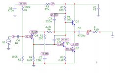
Shamron, I have made a PCB for this particular amp this afternoon to see if I can help you and build it up probably tomorrow if you still have no luck with the info below. I had a JHL in the early eighties probably, but has since moved on.
In the mean while see if you measure these DC voltages from the simulation, I used the component values for an 8 ohm speaker and the 28V supply rail. P.S. no signal just DC.
Note: If you find the fault I will not bother to build it, so I will wait on your response.
In the mean while see if you measure these DC voltages from the simulation, I used the component values for an 8 ohm speaker and the 28V supply rail. P.S. no signal just DC.
Note: If you find the fault I will not bother to build it, so I will wait on your response.
Attachments
Yes, like AndrewT indicated, the series connected transformer primary jumper should NOT be grounded - remember one of those primary connections is off the hot mains winding.
As far as the resistance on speaker ground/power ground/signal ground, it is likely OK. Only thing I can think of is that 10k resistor that is not in original circuit, is preventing the bias from being set higher...it appears to connect speaker output to ground. Why? If it was a Zobel it would have a cap in series to ground, and a different value resistor.
But what's the purpose of the 10K resistor in paralell with the speaker? To provide some stable resistance to help take care of oscillation?
Hmm... It's tempting to try to remove it. Anyone got a suggestion wether to do it or not?
@Nico: Thanks for the help, i will measure my voltages tomorrow or monday and get back to you.
Last edited:
@John65b: I have looked at the schematics from the 96 update and Hood uses a 1K resistor there. On earlier and later revisions, it's non-existant.
What is its purpose? To reduce the risk of oscillation, or to give the amplifier some sort of load even if no speaker is connected?
I decided to solder it out but it didn't change anything. When i rested my hand close to the input capacitor, i could hear hiss and when i accidentaly touched one of the leads on it, i heard a loud squeeking sound in the speaker. I've heard noise when coming close to the early signal path before, but this sounded like oscillation. Not sure if it was because the resistor was gone or just superstition.
Oh well, soldering it back in.
@Nico: Should i do those measurements with a speaker connected, or not? I do have a 100W 8Ohm resistor ment to "emulate" a speaker (without the impedance ofc) so i don't ruin a speaker while experimenting. :-D
I am running it on 27V, not 28V. Should i adjust or doesn't it matter? Also, your schematic have some minor differences from the 1969 JLH. the 470uF and the 12pF capacitors. Also, your output capacitor is 4700uF while as the 1969 article says 2500uF for 8Ohm.
Questions comes from my lack of experience
Thanks for continued help, i'll see if i have those measurements soon.
Here is the amp with my preamp on top. A friend milled the volume knob for me and the volume control is a 128-steps relay volume control. It's kinda fun actually, hearing the clicks from the relays when you turn the volume up or down.
http://img706.imageshack.us/img706/7973/20111009022105.jpg
Ok, initiating measurement...ness.
Ben.-
Nico
Would it be possible for you to post the pcb-layout that you use?
Regards, Torben
Hi Torben. I posted a link to pics of it in post 26 in this thread but i'll post them again here.
eBay - New & used electronics, cars, apparel, collectibles, sporting goods & more at low prices
It's the best pic i got without dismantling the amplifier.
- Status
- This old topic is closed. If you want to reopen this topic, contact a moderator using the "Report Post" button.
- Home
- Amplifiers
- Solid State
- What am i doing wrong, why wont my JLH operate in class A / get warm?