Hello!
I was wondering why nobody did not try diamond buffer built of mosfets? or did not write about it? Is it obvious?
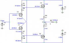
Please look at the circuit.
The first pair is IRF540/9540 (or any low power mosfets pair), output pair IRFP140/9240.
Large heatsinks have to be used.
I only do not know if there is a need to mount all of the mosfets on it, or only 140/9240? In this case small heatsinks should be use for 540/9540.
I was wondering why nobody did not try diamond buffer built of mosfets? or did not write about it? Is it obvious?
Please look at the circuit.
The first pair is IRF540/9540 (or any low power mosfets pair), output pair IRFP140/9240.
Large heatsinks have to be used.
I only do not know if there is a need to mount all of the mosfets on it, or only 140/9240? In this case small heatsinks should be use for 540/9540.
Attachments
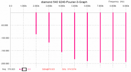
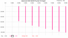
distortion distribution at 1V~
Please look at the simulation results, input voltage = 1V~, output almost the same.
Nice distribution!
Large offset might be a problem, maybe there will be necessary to use a DC-servo?
However 0.1 Ohm resistors stabilises output current during changing of the temperature.
Besides some amplifiers have at the output +-0.6V DC.
Attachments
Upupa Epops said:...poor efficiency
yes, indeed, class A has poor efficiency!

Upupa Epops said:poor temperature stability
not so poor!
Upupa Epops said:big input capacity
only low output impedance preamp is needed!
Upupa Epops said:big distortion
what???
where???
did you see the graphs?
I think this is very good result for non global NFB circuit!!
I could bet that the sound will be better than in conventional circuits (GNFB).
Upupa Epops said:All is nonsens, ...stay on earth
sorry I cannot

better join my heaven
peranders said:I can't find very much good, can you help me here?
maybe not very much good,
but good:
1. low distortion
2. good harmonic character
3. simplicity
4. relatively high power as for a class A
not much? maybe.
sending this circuit on the forum I was curious about possible improovments proposed by the members.
I do not think that it is a top

I thought that it will be a nice gift for the tests and improovments, but does not?

anyway, during this weekend I am going to build it!
High input capacity? Note that these parts are used as followers, Cgs does not come into equation. Driven with a decent frontend, this is not an issue.
Btw, Padamiecki, take the IRF610 and 9610 for input, they have even much lower capacitance.
Also, I think you should use IRFP240/9140 for output, not the other way around. They are a better complement.
It would be maybe better to feed the input FET's with a constant current source (replace R1+R2 with ccs), that way the source resistors will drop a more constant voltage.
Thermal stability should be OK, when you fit the input FET's to the same heatsink as the output FET's.
P-A,
"why a MOS-FET diamond buffer?"
I may ask you, why a BJT diamond buffer?
In both cases, I find it an elegant way to bias the output stage, while at the same time having the current boost of a driver stage.
Btw, regarding efficiency: This is better efficiency than using a source follower driver stage. You can swing closer to the rails.
Go for it, Padamiecki, and report the results.
Tino
Maybe I should ask what are you going to use it for?
Which currents do you have in mind? EDIT: 1.7 A Wow.
A few possible drawbacks:
Lower transconductance => more distortion, higher output impedance
Unpredictable Vgs, needs carefull matching
Very unlinear capacitance behavoiur => distortion maybe
Lot's of output offset (may not be a problem though)
Much more temperature coefficient, -10 mV/ deg vs. -2 mV/deg
Much more input capacitance, possibility to reduced bandwidth.
If you really want to know, just do some P2P experimenting.
I maybe be totally wrong you know.
zinsula said:High input capacity? Note that these parts are used as followers, Cgs does not come into equation. Driven with a decent frontend, this is not an issue.
Btw, Padamiecki, take the IRF610 and 9610 for input, they have even much lower capacitance.
thanks
zinsula said:It would be maybe better to feed the input FET's with a constant current source (replace R1+R2 with ccs), that way the source resistors will drop a more constant voltage.
yes but I wanted the simplicity
besides there are many posts that a resistors sounds the best
zinsula said:Thermal stability should be OK, when you fit the input FET's to the same heatsink as the output FET's.
this is what I was waiting for
zinsula said:P-A,
"why a MOS-FET diamond buffer?"
I may ask you, why a BJT diamond buffer?
In both cases, I find it an elegant way to bias the output stage, while at the same time having the current boost of a driver stage.
Btw, regarding efficiency: This is better efficiency than using a source follower driver stage. You can swing closer to the rails.
Go for it, Padamiecki, and report the results.
Tino
this means: "go for it and kick some a******?"
I will try my best to finish this project untill Monday
mo¿e to Cie zainteresuje:
http://www.diyaudio.com/forums/showthread.php?postid=676949#post676949
http://www.diyaudio.com/forums/showthread.php?postid=676949#post676949
darkfenriz said:mo¿e to Cie zainteresuje:
http://www.diyaudio.com/forums/showthread.php?postid=676949#post676949
super!
thanks!
how to avoid this DC source at the input?
bjt EF?

padamiecki said:this means: "go for it and kick some a******?"
Hehe, that is your interpretation....maybe not too far away....
Well, I just wanted to encourage you.
This is something I had in mind, with frontend similar to this:
http://www.diyaudio.com/forums/attachment.php?s=&postid=614603&stamp=1112908994
NP gave "absolution":
http://www.diyaudio.com/forums/showthread.php?postid=723517#post723517
Obviously with increased rail voltage, and two of the following buffers...
Uh, and do not forget gate stoppers!

Success, Tino
Attachments
Tim__x said:I assume that -100db distortion can only be obtained in heavy class-A bias?
Yes, but not so big problem for a link stage. A diamond buffer as a class A power amp also brings very low level of distortion, like here:
http://web.telecom.cz/macura/pma1_1w_8o.gif
This one has 2 transistors added in the output stage, connected as CFP, this reduces distortion again.
- Status
- This old topic is closed. If you want to reopen this topic, contact a moderator using the "Report Post" button.
- Home
- Amplifiers
- Solid State
- what about diamond buffer MOSFET?