Hi all
I have to thank all of you, who have provided your knowledge, have described your practices and have expressed your opinions here. I hope that my intervening will not upset you much.
I have asked two questions so far.
The first question was:
Is it possible from impedance versus frequency data sets to reverse engineer (construct) the electrical network from L,C,Rs (equivalent circuit) which will exactly model a speaker in some form of installation?
To this question, the most straightforward answer is to me, the answer of Conrad Hoffman: I don't know if there's any foolproof deterministic way to do this.
Utilisation of “foolproof” and “deterministic” is as precise as a mathematical formula of the Set Theory, and that was what I implied with my question.
Intuitively, I am optimistic as to the “deterministic’ part. The “foolproof” is that may bring some doupts.
So far, this “I don’t know” still holds.
On the other hand, such an impedance curve (it’s data sets) can be modelled by a “n” order polynomial equation (provided it is continuous and it does not have sharp kinks)
During my search, I found EISA EIS Spectrum Analyser a free program for analysis and simulation of impedance spectra, a tool used in Potentiodynamic Electrochemical Impedance Spectroscopy
Dielectric spectroscopy - Wikipedia, the free encyclopedia (a field familiar to SY and Jackini I guess. *PS)
The program seems quite promising. When I will manage to work all it’s functions, I will let you know.
On the same topic: Does anyone of you know if the program Boxcad - part of Bodgio SW “Soundeasy”- Home Page
imports Impedance measurement data and through this, produces an editable L,C,Rs equivalent circuit ?
The second question was:
What do you think? Are the published speaker/enclosure equivalent circuits detailed enough to let us model speakers over an extended frequency range, or there is a need for a more precise customized model generation ?
Here I have the pleasure to read a lot of useful information given by LineArray and gedlee (thank you both).
LineArray seems to be very cautious when using an equivalent L,C,R circuit, knowing the limitations of the modelling. He is also not modelling the acoustical load (“everything on the mechanic to acoustic side - is completely out of scope of such a model.”) probably due to the inadequacy of utilised models.
Gedlee is certain that everything should be included in a utilized model, but such a model can not be restricted to L,C,Rs alone. I hope that more explanations will be kindly provided.
I am certain that LineAray is doing the proper thing with the current (known) state of simulation. I think that he would’t mind if I ask for a contribution from the members of some more speaker/enclosure models, so we can have a discussion of their pros/cons.
I also wish that gedlee has the advanced solution to bring the art of simulation, a step further.
(And although I haven’t reached the limits of speakers modelling thru L,C,Rs") , I always wondered if the model of the L and the model of the C take into account the energy storage/delayed release property of these electrical elements)
, I always wondered if the model of the L and the model of the C take into account the energy storage/delayed release property of these electrical elements)
Best Regards
George
*PS But the 3 electrode measurement method, is also the one used by electricians to measure the impedance of the safety ground bar, isn’t it?
I have to thank all of you, who have provided your knowledge, have described your practices and have expressed your opinions here. I hope that my intervening will not upset you much.
I have asked two questions so far.
The first question was:
Is it possible from impedance versus frequency data sets to reverse engineer (construct) the electrical network from L,C,Rs (equivalent circuit) which will exactly model a speaker in some form of installation?
To this question, the most straightforward answer is to me, the answer of Conrad Hoffman: I don't know if there's any foolproof deterministic way to do this.
Utilisation of “foolproof” and “deterministic” is as precise as a mathematical formula of the Set Theory, and that was what I implied with my question.
Intuitively, I am optimistic as to the “deterministic’ part. The “foolproof” is that may bring some doupts.
So far, this “I don’t know” still holds.
On the other hand, such an impedance curve (it’s data sets) can be modelled by a “n” order polynomial equation (provided it is continuous and it does not have sharp kinks)
During my search, I found EISA EIS Spectrum Analyser a free program for analysis and simulation of impedance spectra, a tool used in Potentiodynamic Electrochemical Impedance Spectroscopy
Dielectric spectroscopy - Wikipedia, the free encyclopedia (a field familiar to SY and Jackini I guess. *PS)
The program seems quite promising. When I will manage to work all it’s functions, I will let you know.
On the same topic: Does anyone of you know if the program Boxcad - part of Bodgio SW “Soundeasy”- Home Page
imports Impedance measurement data and through this, produces an editable L,C,Rs equivalent circuit ?
The second question was:
What do you think? Are the published speaker/enclosure equivalent circuits detailed enough to let us model speakers over an extended frequency range, or there is a need for a more precise customized model generation ?
Here I have the pleasure to read a lot of useful information given by LineArray and gedlee (thank you both).
LineArray seems to be very cautious when using an equivalent L,C,R circuit, knowing the limitations of the modelling. He is also not modelling the acoustical load (“everything on the mechanic to acoustic side - is completely out of scope of such a model.”) probably due to the inadequacy of utilised models.
Gedlee is certain that everything should be included in a utilized model, but such a model can not be restricted to L,C,Rs alone. I hope that more explanations will be kindly provided.
I am certain that LineAray is doing the proper thing with the current (known) state of simulation. I think that he would’t mind if I ask for a contribution from the members of some more speaker/enclosure models, so we can have a discussion of their pros/cons.
I also wish that gedlee has the advanced solution to bring the art of simulation, a step further.
(And although I haven’t reached the limits of speakers modelling thru L,C,Rs
, I always wondered if the model of the L and the model of the C take into account the energy storage/delayed release property of these electrical elements)Best Regards
George
*PS But the 3 electrode measurement method, is also the one used by electricians to measure the impedance of the safety ground bar, isn’t it?
Last edited:
I can not figure this thread out so I will ask the simple question
Is everyone saying that something like WT2 or WT3 purchased from parts express is not good enough for obtain T/S parameters and impedance curves?
doug20
To answer your simple question:
I am certain that All software packages (if they claim so) are absolutelly capable to plot impedance curves and obtain T/S parameters.
No one questioned this here.
Best Regards
George
Hi all
A side note to that:
Due to my ex-professional involvement with Non-Destructive Testing (NDT) on airplanes, I have witnessed the progress in simulations on some of the NDT methods (Ultrasonics, Radiography, Eddy Currents, Acoustic Emission, Thermography).
Some 15 years ago, the simulation packages were producing such gross results that someone was asking himself “what’s the use of these products?”.
Now, the outcome of the simulators is so detailed and so multifacial, that the results from actual -on the field- testing, find it hard to match them. Only testing under laboratory conditions can persistently provide such quality results.
The reason for such a progress on simulation is the massive worldwide –university based – research, still in progress.
There is a strong financial drive for such an activity. Power generation, Aerospace, General industry sectors and medical sector (imaging diagnostics) are the potential customers.
Audio equipment industry may not have such promising financial outcome for to sponsor equal or lesser research for acoustics on loudspeakers.
So, my understanding is that technical knowledge does exist for to build a very precise and detailed loudspeaker simulator. What might hinder a realisation of such a simulator (or the incorporation/adaptation of simulators from other fields), is the weak or non existent financial drive.
Best regards
George
Intuitively, I am optimistic as to the “deterministic’ part. The “foolproof” is that may bring some doupts.
A side note to that:
Due to my ex-professional involvement with Non-Destructive Testing (NDT) on airplanes, I have witnessed the progress in simulations on some of the NDT methods (Ultrasonics, Radiography, Eddy Currents, Acoustic Emission, Thermography).
Some 15 years ago, the simulation packages were producing such gross results that someone was asking himself “what’s the use of these products?”.
Now, the outcome of the simulators is so detailed and so multifacial, that the results from actual -on the field- testing, find it hard to match them. Only testing under laboratory conditions can persistently provide such quality results.
The reason for such a progress on simulation is the massive worldwide –university based – research, still in progress.
There is a strong financial drive for such an activity. Power generation, Aerospace, General industry sectors and medical sector (imaging diagnostics) are the potential customers.
Audio equipment industry may not have such promising financial outcome for to sponsor equal or lesser research for acoustics on loudspeakers.
So, my understanding is that technical knowledge does exist for to build a very precise and detailed loudspeaker simulator. What might hinder a realisation of such a simulator (or the incorporation/adaptation of simulators from other fields), is the weak or non existent financial drive.
Best regards
George
Last edited:
Thanks, I was just curious about the discussion and trying to figure out what the goal was.
doug20
This thread started with a question of the theoretical possibility to model a loudspeaker from data obtained through measurement of it’s complex impedance versus frequency sweep (kind of the possibility to model the character of a person from behavioral data obtained during his/her sexual intercourse
)Regards
George
The first question was:
Is it possible from impedance versus frequency data sets to reverse engineer (construct) the electrical network from L,C,Rs (equivalent circuit) which will exactly model a speaker in some form of installation?
...
Hi gpapag,
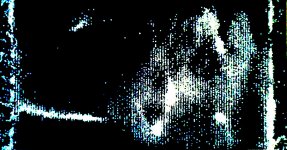
coming from something like the diagram, of course including phase
information, and deriving something like the pictures A...F seems
like "mission impossible" IMO.
A very realistic FEM model of the membrane, all its material
properties and suspension conditions is needed to calculate
the driving point impedance.
The driver itself with elasticity of bonding to the membrane,
its mass and resistances has to be included.
Some of the modes shown will radiate efficiently, some very
weak. But no significant difference in Q of the driving point
resonances will indicate that.
To simulate the radiation, knowledge of velocities using a fine
mesh of reference points over the membrane area is needed.
Kind Regards
Attachments
-
 A_27_Hz.jpg138.9 KB · Views: 238
 -
 B_56_Hz.jpg136.3 KB · Views: 140
 -
 C_74_Hz.jpg114 KB · Views: 139
 -
 D_83_Hz.jpg170 KB · Views: 133
 -
 E_105_Hz.jpg239.1 KB · Views: 134
 -
 F_115_Hz.jpg260.2 KB · Views: 36
 -
 G_140_Hz.jpg278.2 KB · Views: 25
 -
 H_175_Hz.jpg211.3 KB · Views: 30
 -
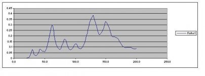 diagram.JPG21.9 KB · Views: 25
Last edited:
doug20
This thread started with a question of the theoretical possibility to model a loudspeaker from data obtained through measurement of it’s complex impedance versus frequency sweep (kind of the possibility to model the character of a person from behavioral data obtained during his/her sexual intercourse
Regards
George
Thanks, I figured that out (Slowly). I once asked a simple man's question if we could create software that could build a great speaker XO just from quality measurements so Im hoping it happens some day.
Hi Oliver
Is this cone flexure visible through laser scanning interferometry or through white dust spreading?
FEM: Now we cross a line here, but this may be what Mr. Geddes hints to in #19 post.
"FEMLAB"
FEMLAB
now "COSMOL"
Multiphysics Modeling and Simulation - COMSOL
One of the many applications published on their site.
http://cds.comsol.com/access/dl/papers/6927/Hedges_pres.pdf
I agree.
But we are steping outside of the diy realms (the line crossing)
Best Regards
George
Is this cone flexure visible through laser scanning interferometry or through white dust spreading?
FEM: Now we cross a line here, but this may be what Mr. Geddes hints to in #19 post.
"FEMLAB"
FEMLAB
now "COSMOL"
Multiphysics Modeling and Simulation - COMSOL
One of the many applications published on their site.
http://cds.comsol.com/access/dl/papers/6927/Hedges_pres.pdf
A very realistic FEM model of the membrane, all its material
properties and suspension conditions is needed to calculate
the driving point impedance.
The driver itself with elasticity of bonding to the membrane,
its mass and resistances has to be included.
Some of the modes shown will radiate efficiently, some very
weak. But no significant difference in Q of the driving point
resonances will indicate that.
To simulate the radiation, knowledge of velocities using a fine
mesh of reference points over the membrane area is needed.
I agree.
But we are steping outside of the diy realms (the line crossing)
Best Regards
George
Last edited:
And for Your intellectual entertainment
http://www.bwspeakers.com/downloadFile%5CtechnicalFeature%5C800_Development_Paper.pdf
Best Regards
George
http://www.bwspeakers.com/downloadFile%5CtechnicalFeature%5C800_Development_Paper.pdf
Best Regards
George
Hi Oliver
Is this cone flexure visible through laser scanning interferometry or through white dust spreading?
...
Just a test sheet with node lines
made visible using couscous from the kitchen ...
Hi George,
You CAN get an exact model, HOWEVER, it is only valid at the precise excitation level used to take the measurements (plus some other limitations)...
In real speakers you will find that many of the terms that are shown as simple capacitors and inductors and even resistor in electrical equivalent schematic will change significantly with frequency and level.
In my view the main issues are in no particular order are:
Suspension Nonlinearity [aka Km(x)]
Magnet Field Nonlinearity [aka BL(x) and BL(i)]
Voice coil inductance Nonlinearty [aka Le(x) and Le(i)]
Voice Coil Resistance nonlinearity [aka Re(i)]
In this notation, i denotes nonlinearities are a function of voice coil current and x denotes those that are related to mechanical excursion.
Once we look at the coupling of of the mechanical system to electrical system we note the coupling is not wholly linear and rigid, but lossy. So the fact that we generate a "microphone" Voltage by moving the voice coil (aka Back EMF, see Lenz), we must understand that the magnet field in the gap is being modulated by the field created by the voice coil and there are the coupling losses so there are complex intermodulations happening.
Hence the so called Back EMF is more or less heavily distorted and not a good representation of what actually happens at the cone. In fact, getting involved with voltages where speakers are concerned is counter-productive and misleading, hence you see no voltage related terms at all.
Most of the non-linearity terms are monotonic, meaning the fall proportionally to the exciting quantity(except mechanical suspension hysteresis), so testing speakers for their (TS) parameters is often done at low power levels (like 1mW). The problem is that the small signal model is not very representative of the the large signal conditions, as they deliberately exclude or at least drastically minimise all the non-linearities.
On the surface it seems trivial to model speakers, yet those sufficiently well educated to actually understand the matter deeper find it a complex and difficult thing.
As another note, all the ..(i) distortion terms may be cancelled out by switching from voltage source drive of the speaker to current source drive and addressing the other consequences of doing so (frequency response changes).
All ..(x) terms require fundamental adjustments to driver design, but they can of course be minimised by simply minimising (x)... I tend to quip that if you can see the driver moving for bass frequencies you should have used more drivers or larger ones...
So using large size pro drivers and current drive could for example make for a system with dramatically better linearity than common "High End" or "High Fidelity" systems. Maybe that is why I liked my 15" Tannoy Corner Yorks and Tube AMp's so much...
Ciao T
We are able to plot the impedance versus frequency of a speaker either in air or installed on an enclosure.
We can thus have a set of impedance parameters of this speaker for every frequency in Z (Ohm) and V to I Phase Angle (degrees) data, or in R, Zl, Zc (Ohms) and Zx to R Phase Angle (degrees).
Is it possible from all these data sets to reverse engineer (construct) the electrical network from L,C,Rs (equivalent circuit) which will exactly model this speaker in this very installation?
You CAN get an exact model, HOWEVER, it is only valid at the precise excitation level used to take the measurements (plus some other limitations)...
In real speakers you will find that many of the terms that are shown as simple capacitors and inductors and even resistor in electrical equivalent schematic will change significantly with frequency and level.
In my view the main issues are in no particular order are:
Suspension Nonlinearity [aka Km(x)]
Magnet Field Nonlinearity [aka BL(x) and BL(i)]
Voice coil inductance Nonlinearty [aka Le(x) and Le(i)]
Voice Coil Resistance nonlinearity [aka Re(i)]
In this notation, i denotes nonlinearities are a function of voice coil current and x denotes those that are related to mechanical excursion.
Once we look at the coupling of of the mechanical system to electrical system we note the coupling is not wholly linear and rigid, but lossy. So the fact that we generate a "microphone" Voltage by moving the voice coil (aka Back EMF, see Lenz), we must understand that the magnet field in the gap is being modulated by the field created by the voice coil and there are the coupling losses so there are complex intermodulations happening.
Hence the so called Back EMF is more or less heavily distorted and not a good representation of what actually happens at the cone. In fact, getting involved with voltages where speakers are concerned is counter-productive and misleading, hence you see no voltage related terms at all.
Most of the non-linearity terms are monotonic, meaning the fall proportionally to the exciting quantity(except mechanical suspension hysteresis), so testing speakers for their (TS) parameters is often done at low power levels (like 1mW). The problem is that the small signal model is not very representative of the the large signal conditions, as they deliberately exclude or at least drastically minimise all the non-linearities.
On the surface it seems trivial to model speakers, yet those sufficiently well educated to actually understand the matter deeper find it a complex and difficult thing.
As another note, all the ..(i) distortion terms may be cancelled out by switching from voltage source drive of the speaker to current source drive and addressing the other consequences of doing so (frequency response changes).
All ..(x) terms require fundamental adjustments to driver design, but they can of course be minimised by simply minimising (x)... I tend to quip that if you can see the driver moving for bass frequencies you should have used more drivers or larger ones...
So using large size pro drivers and current drive could for example make for a system with dramatically better linearity than common "High End" or "High Fidelity" systems. Maybe that is why I liked my 15" Tannoy Corner Yorks and Tube AMp's so much...
Ciao T
Thorsten
Thank you for dropping in. I appreciate your comments.
I have purchased the book Amazon.com: Current-Driving of Loudspeakers: Remedy to the Fundamental Fallacy of Sound Reproduction Technology (9781448695324): Esa Meriläinen: Books written by our forum member ETM. The first 4 chapters helped me understand much better what is really going on inside the motor part of a driver, all these crucial details like you write above.
As for the Back EMF Signal, I remember there is at least one article in one of the early volumes of AES Anthologies and Monographs that deals with methods of isolating and monitoring this signal. I haven’t dealt with it (yet), so I have nothing to add.
Now for the subject under investigation here:
The mention of the influence of the excitation level on the model is very important. Good that you made this remark.
Then, restricting ourselves working with a constant amplitude and small excitation level, which is the way to get a well representative – if not exact – model from the electrical impedance data ?
I mean, do you know of some method that takes in Impedance data and generates an equivalent electrical model (furthermore assigning values to the various L, C, Rs ) as an output?
Or is this bound to remain an iterative – solely - manual process, where one adopts a model, assigns element values to it, simulates it, and readjusts, until the simulated impedance data comes close to the measured impedance data?
Regards
George
Thank you for dropping in. I appreciate your comments.
I have purchased the book Amazon.com: Current-Driving of Loudspeakers: Remedy to the Fundamental Fallacy of Sound Reproduction Technology (9781448695324): Esa Meriläinen: Books written by our forum member ETM. The first 4 chapters helped me understand much better what is really going on inside the motor part of a driver, all these crucial details like you write above.
As for the Back EMF Signal, I remember there is at least one article in one of the early volumes of AES Anthologies and Monographs that deals with methods of isolating and monitoring this signal. I haven’t dealt with it (yet), so I have nothing to add.
Now for the subject under investigation here:
You CAN get an exact model, HOWEVER, it is only valid at the precise excitation level used to take the measurements (plus some other limitations)...
The mention of the influence of the excitation level on the model is very important. Good that you made this remark.
Then, restricting ourselves working with a constant amplitude and small excitation level, which is the way to get a well representative – if not exact – model from the electrical impedance data ?
I mean, do you know of some method that takes in Impedance data and generates an equivalent electrical model (furthermore assigning values to the various L, C, Rs ) as an output?
Or is this bound to remain an iterative – solely - manual process, where one adopts a model, assigns element values to it, simulates it, and readjusts, until the simulated impedance data comes close to the measured impedance data?
Regards
George
Hi,
It is covered by the various textbooks. The basic impedance will be a resistor and lossy inductor in series with it. To this you may need to add a lossy transformer through which you couple the LRC Circuit that models that mass/spring resonant system.
Any other resonances may need additional such systems. So this gives you the basic electrical schematic of the network. The values of most items can be calculated based on the usual formulas (that is what textbooks are for, I normally use the stuff from Ted Jordans article in WW...).
And as all these resonant and other impedance modifying systems are lossy you need to account for these losses. This all may have to be iterative as there are invariably variables that if they change require others to be adjusted which in turn force the original value to corrected again.
It is not that difficult to program suitable curve fitting algorithms that you can simply crunch numbers until things converge to your set limits. Non-convergence simply means you have to add more elements to the equivalence circuit or set a greater tolerance on your acceptable limits.
My question would be what the purpose of this model is.
If it has a practical purpose (other than intellectual curiosity and too much time to engage in lucubrations) knowing this purpose may be usable in understanding what level of complexity and precision your model needs.
For example, in the simulation software I use no attempt in the traditional sense is made to create a model of the impedance, but impedance data is taken directly, as impedance and impedance phase and used in calculations.
If the model is complex enough to be of use I would tend towards this view.
The alternative is to use a more primitive model and accept it's shortcomings, know them and work around them (which is what most professionals do - we like better models, but we are okay with what we got).
Ciao T
Then, restricting ourselves working with a constant amplitude and small excitation level, which is the way to get a well representative – if not exact – model from the electrical impedance data ?
It is covered by the various textbooks. The basic impedance will be a resistor and lossy inductor in series with it. To this you may need to add a lossy transformer through which you couple the LRC Circuit that models that mass/spring resonant system.
Any other resonances may need additional such systems. So this gives you the basic electrical schematic of the network. The values of most items can be calculated based on the usual formulas (that is what textbooks are for, I normally use the stuff from Ted Jordans article in WW...).
And as all these resonant and other impedance modifying systems are lossy you need to account for these losses. This all may have to be iterative as there are invariably variables that if they change require others to be adjusted which in turn force the original value to corrected again.
It is not that difficult to program suitable curve fitting algorithms that you can simply crunch numbers until things converge to your set limits. Non-convergence simply means you have to add more elements to the equivalence circuit or set a greater tolerance on your acceptable limits.
My question would be what the purpose of this model is.
If it has a practical purpose (other than intellectual curiosity and too much time to engage in lucubrations) knowing this purpose may be usable in understanding what level of complexity and precision your model needs.
For example, in the simulation software I use no attempt in the traditional sense is made to create a model of the impedance, but impedance data is taken directly, as impedance and impedance phase and used in calculations.
Or is this bound to remain an iterative – solely - manual process, where one adopts a model, assigns element values to it, simulates it, and readjusts, until the simulated impedance data comes close to the measured impedance data?
If the model is complex enough to be of use I would tend towards this view.
The alternative is to use a more primitive model and accept it's shortcomings, know them and work around them (which is what most professionals do - we like better models, but we are okay with what we got).
Ciao T
Hi Thorsten
Thanks for the input.
A normal diy itch
http://www.diyaudio.com/forums/multi-way/166184-what-idea-shoot-him.html#post2180546
Regards
George
Thanks for the input.
My question would be what the purpose of this model is.
If it has a practical purpose (other than intellectual curiosity and too much time to engage in lucubrations) knowing this purpose may be usable in understanding what level of complexity and precision your model needs.
A normal diy itch
http://www.diyaudio.com/forums/multi-way/166184-what-idea-shoot-him.html#post2180546
My wish is, this electrical circuit that is born out of the measured electrical impedance of the driver/enclosure, to be used to study the effect that the value of each component has on the outcome. Also, to calculate/simulate the acoustic frequency response of this driver/enclosure..
There are some less demanding utilizations of this model, e.g. the study of the amplifier and/or x-over interaction with this model.
Regards
George
Hi,
Any model that is more than a crude first order approximation is going to be very complex.
For DIY it may be easier to just measure the darn driver and use the data directly in suitable programs. If you want to do a basic feasibility study, normal small signal TS stuff may be used for a good first order approximation.
If you want to test amplifiers with speaker equivalent loads, take a page out of respectively Matti Ottala's and John Atkinson's books (or maybe it's my book?).
Take two real speakers, make sure pair matching is good (see Blowtorch thread on how I do that) and then place face to face and test with mono-test signals where one channel has inverted polarity.
This keeps the noise fairly down and you can test almost anything, including listening to the residue of cancelled music (e.g. SE Amplifiers are very interresting). It is important to invert test signal polarity and not the speaker cables polarity for this, BTW...
Ciao T
A normal diy itch
Any model that is more than a crude first order approximation is going to be very complex.
For DIY it may be easier to just measure the darn driver and use the data directly in suitable programs. If you want to do a basic feasibility study, normal small signal TS stuff may be used for a good first order approximation.
If you want to test amplifiers with speaker equivalent loads, take a page out of respectively Matti Ottala's and John Atkinson's books (or maybe it's my book?).
Take two real speakers, make sure pair matching is good (see Blowtorch thread on how I do that) and then place face to face and test with mono-test signals where one channel has inverted polarity.
This keeps the noise fairly down and you can test almost anything, including listening to the residue of cancelled music (e.g. SE Amplifiers are very interresting). It is important to invert test signal polarity and not the speaker cables polarity for this, BTW...
Ciao T
Then, restricting ourselves working with a constant amplitude and small excitation level, which is the way to get a well representative – if not exact – model from the electrical impedance data ?
I mean, do you know of some method that takes in Impedance data and generates an equivalent electrical model (furthermore assigning values to the various L, C, Rs ) as an output?
Or is this bound to remain an iterative – solely - manual process, where one adopts a model, assigns element values to it, simulates it, and readjusts, until the simulated impedance data comes close to the measured impedance data?
Regards
George
Assigning values to an equivalent circuit is generally an itterative process but can use automatic optimizers. We used to take this approach at KEF for deriving Thiele/Small parameters. We had our own software but today a number of CAD programs can do the optimization. Typically you define a circuit topology that should work, assign some starting values and let it chug away. Some optimizers are better than others and can get there even if your starting values are poor. People that do this a lot know the tricks like freezing some components while the others optimize.
At KEF we would always divide the two curves (measured and optimized) and multiply times 10 to examine the error. Generally the error curve is due to an oversimplified model.
For the woofer box there were always two residual errors when using the standard model. There was an s shaped error around the tip of resonance and there was poor fit to the inductance rise. The first error is from a phenomonon known as "creep" which is a low speed stretch of the suspension elements that makes the resonance slightly non-symmetrical (hence the "S" shaped assymetry).
The inductance rise can't be well fit with a single L and R, but can be better fit with a series of Ls and shunting Rs. It can be exactly fit with inclusion of a frequency dependent resistor.
I would think you could manually fit to an impedance curve to an adequate degree. The curve is simple and you can soon learn how each component impacts the model.
The comment was made that most woofer box calculators model the equivalent circuit. I suspect that most manipulate the equations behind the circuit. There is no reason to deal with Farads and Henrys. (A fine point)
Regards,
David
Thank you David (sorry for this late response)
Thorstern:
I'd love to read a book of yours. Any link to it?
Can you please explain why?
Regards
George
Thorstern:
(or maybe it's my book?)
I'd love to read a book of yours. Any link to it?
It is important to invert test signal polarity and not the speaker cables polarity for this, BTW...
Can you please explain why?
Regards
George
Hi,
Sorry, no time yet to write them. I have outlines for a few novels, what holds me back is that I am probably an excellent reader, but that does not make an equally excellent, or even good writer...
Usually the SPL cancellation is greater that way, due to speaker nonlinearities...
Ciao T
I'd love to read a book of yours. Any link to it?
Sorry, no time yet to write them. I have outlines for a few novels, what holds me back is that I am probably an excellent reader, but that does not make an equally excellent, or even good writer...
Can you please explain why?
Usually the SPL cancellation is greater that way, due to speaker nonlinearities...
Ciao T
Usually the SPL cancellation is greater that way, due to speaker nonlinearities...
Do you mean "due to speaker cable nonlinearities" ?
what holds me back is that .....
There would be a problem, if such concerns were not holding you back
. Thus, i'll waitGeorge
- Status
- This old topic is closed. If you want to reopen this topic, contact a moderator using the "Report Post" button.
- Home
- Loudspeakers
- Multi-Way
- What a *@#$%^& Idea! Shoot him!