
Noise
Hello all,
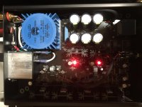
I just noticed some noise on this amp. The noise only comes when there is no source connection (nothing plugged in) and the volume is turned 3/4 to all the way up. I have a 0.1mf cap between the chassis ground and the negative leads of the RCA jacks. Should I try larger cap (maybe 0.47mf) or put another cap between the chassis and the ground of the volume pot?
Otherwise, when a source component plugged in, the amp is dead quiet and sounds great.
Thank you for your input.
Hello all,
I just noticed some noise on this amp. The noise only comes when there is no source connection (nothing plugged in) and the volume is turned 3/4 to all the way up. I have a 0.1mf cap between the chassis ground and the negative leads of the RCA jacks. Should I try larger cap (maybe 0.47mf) or put another cap between the chassis and the ground of the volume pot?
Otherwise, when a source component plugged in, the amp is dead quiet and sounds great.
Thank you for your input.
Would it make sense to alter anything to accommodate a 'no source' problem scenario? When would you want to 'listen' to no source? If the amp is noisy with a source, then I would go to lengths to fix it. But I wouldn't try and change things happening without a source.
That's just me though, obviously!
My parts kit is arriving tomorrow! Really excited about it.
Rafa.
That's just me though, obviously!
My parts kit is arriving tomorrow! Really excited about it.
Rafa.
Would it make sense to alter anything to accommodate a 'no source' problem scenario? When would you want to 'listen' to no source? If the amp is noisy with a source, then I would go to lengths to fix it. But I wouldn't try and change things happening without a source.
That's just me though, obviously!
My parts kit is arriving tomorrow! Really excited about it.
Rafa.
I agree. I was only wondering if that noise was normal. This amp is great.
It might just do that because the input is pretty high impedance unterminated.
Thanks Wayne for sharing all the knowledge and helping out.
Oh my, thank you so much...
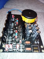
aheck, also check your R18 and R30. Looks like you might have swapped the 100K's into those positions which should be the 100 ohm you used in R3 and R5.
Well, got my Parts Kit! Nicely done! A really thoughtful package. A particular nice touch is the addition of the DIP socket to allow for quick OpAmp testing.
I'll take a bit of time preparing my kit (again I need to figure out the best chassis approach, size, distribution, etc.)... so I am probably going to have a lot of questions along the way.
I have two right off the bat and that is:
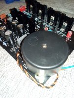
- Why are such long hex stand offs provided with the Kit? The included 1" stands really elevate the PCB quite a bit more than what I would have expected. Also, they make for a less 'steady' construction if the board is not 'anchored' by its sides. Any insight as to what was the purpose of this or what am I missing with these stand offs? Perhaps air flow? Other than vertical alignment, do you foresee any issue if I use shorter stand offs?
The included Schurter filtered power entry module is massive, and I really appreciate the DIY store for including this! A smaller one would be an easier fit, but I thank for the added filtering capabilities and the solid build of this thing. I really would not change it for a smaller one. But here's my question:
- Since I would be cutting my own chassis, I can distribute things to best suite the Whammy, and not fit the smallest confined space. Conceptually (and given the PCB layout), do you think its better to make a longer case and still place the power entry module 'behind' the Transformer (albeit much further back not to get squashed against the trafo), or is it just the same to move it towards the 'audio' section and prevent the 'longer' case?
Also, I bought some 'redundant' components that could be used as replacement (Nichicon metallic green caps, other-brand regulators, etc.)... so I will be poking your enlightened minds as to what has sense and merit to substitute and what would be just irrelevant.
Really looking forward to these previous-to-build decisions.
Thanks for all the input, best regards,
Rafa.
I'll take a bit of time preparing my kit (again I need to figure out the best chassis approach, size, distribution, etc.)... so I am probably going to have a lot of questions along the way.
I have two right off the bat and that is:
- Why are such long hex stand offs provided with the Kit? The included 1" stands really elevate the PCB quite a bit more than what I would have expected. Also, they make for a less 'steady' construction if the board is not 'anchored' by its sides. Any insight as to what was the purpose of this or what am I missing with these stand offs? Perhaps air flow? Other than vertical alignment, do you foresee any issue if I use shorter stand offs?
The included Schurter filtered power entry module is massive, and I really appreciate the DIY store for including this! A smaller one would be an easier fit, but I thank for the added filtering capabilities and the solid build of this thing. I really would not change it for a smaller one. But here's my question:
- Since I would be cutting my own chassis, I can distribute things to best suite the Whammy, and not fit the smallest confined space. Conceptually (and given the PCB layout), do you think its better to make a longer case and still place the power entry module 'behind' the Transformer (albeit much further back not to get squashed against the trafo), or is it just the same to move it towards the 'audio' section and prevent the 'longer' case?
Also, I bought some 'redundant' components that could be used as replacement (Nichicon metallic green caps, other-brand regulators, etc.)... so I will be poking your enlightened minds as to what has sense and merit to substitute and what would be just irrelevant.
Really looking forward to these previous-to-build decisions.
Thanks for all the input, best regards,
Rafa.
The long standoffs are there to accommodate the thick faceplate in the upcoming chassis. Yes, I understand that answer does not make sense on the surface, but it has to do with the milled-out portion of the faceplate and elevating the PCB for it to fit.
If you make your own chassis, use whatever standoffs you wish.")
The Schurter is fused, switched, filtered, and the important point, all ready wired. That's how big they are. It's a super nice part.
Yes, your thoughts of making the chassis longer is the most logical direction, but more room always makes things easier.
Use the parts in the kit, it's all good stuff. Instead of trying to make some incredibly small difference with passive part choices, make a real modification and 1) add input selection to turn it into a preamp, 2) have a switched output to choose headphone jack or RCA, and, if you are absolutely dying to try different parts, 3) try different opamps, because that will actually make a difference.
If you make your own chassis, use whatever standoffs you wish.
The Schurter is fused, switched, filtered, and the important point, all ready wired. That's how big they are. It's a super nice part.
Yes, your thoughts of making the chassis longer is the most logical direction, but more room always makes things easier.
Use the parts in the kit, it's all good stuff. Instead of trying to make some incredibly small difference with passive part choices, make a real modification and 1) add input selection to turn it into a preamp, 2) have a switched output to choose headphone jack or RCA, and, if you are absolutely dying to try different parts, 3) try different opamps, because that will actually make a difference.
For anybody that is interested I am building up a batch of these and testing them with help from the local high school chamber choir. They have been invited to sing at Carnegie hall in New York City this spring and of course are raising money to get from California to New York. I thought this would help them out compared to the traditional fundraising efforts.
They will be built with sockets for the opamp and Vishay .6 Watt copper leaded resistors and Toshiba outputs. It takes some of the DIY out of it but you can still do the chassis. All the $ go to the trip for these talented students and they are a nonprofit corporation so I think at least some is tax deductible.
They will be built with sockets for the opamp and Vishay .6 Watt copper leaded resistors and Toshiba outputs. It takes some of the DIY out of it but you can still do the chassis. All the $ go to the trip for these talented students and they are a nonprofit corporation so I think at least some is tax deductible.
What a nice idea!For anybody that is interested I am building up a batch of these and testing them with help from the local high school chamber choir. They have been invited to sing at Carnegie hall in New York City this spring and of course are raising money to get from California to New York. I thought this would help them out compared to the traditional fundraising efforts.
They will be built with sockets for the opamp and Vishay .6 Watt copper leaded resistors and Toshiba outputs. It takes some of the DIY out of it but you can still do the chassis. All the $ go to the trip for these talented students and they are a nonprofit corporation so I think at least some is tax deductible.
Ugh, was waiting until pay day to grab a parts kit and they sold out... 🤪
That was just the first batch. There will be more.
- Home
- Amplifiers
- Pass Labs
- "WHAMMY" Pass DIY headphone amp guide