Hi, more experienced diyer,
Please see the attached images.
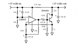
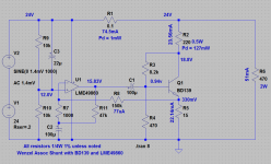
The circuit is from Wenzel associates .
Finesse Voltage Regulator Noise!
I build the shunt hoping to clean up a 24 V dc supply for my pre.
The 2n 4401 becomes too hot to touch after 5 minutes. However, there is no problem if i powered with 12 V dc.
I have checked the spec of 2n 4401 and is within operating range.
What are the values to change to prevent overheating of the 2n 4401 ?
thanks
kp93300
Please see the attached images.
The circuit is from Wenzel associates .
Finesse Voltage Regulator Noise!
I build the shunt hoping to clean up a 24 V dc supply for my pre.
The 2n 4401 becomes too hot to touch after 5 minutes. However, there is no problem if i powered with 12 V dc.
I have checked the spec of 2n 4401 and is within operating range.
What are the values to change to prevent overheating of the 2n 4401 ?
thanks
kp93300
Attachments
If it were me I would switch to a BD139-16, then heat sink it like DF96 said.
http://www.fairchildsemi.com/ds/BD/BD139.pd
http://www.fairchildsemi.com/ds/BD/BD139.pd
...and you need to change the 4300R resistor to 8450R if you are going to feed it with 24V rather than 15V and want to preserve the 18.7mA idle current through the shunt it seems to be designed for. With the 4300R bias resistor you get 40mA through the shunt at 24V, which equates to 14.5V across the transistor and Pd = 580mW, right at the heat-sinked max for that 2n4401.
How much load current do you intend to pull at the 24V? The values seem to be set up for an expected load of around 100-200mA.
How much load current do you intend to pull at the 24V? The values seem to be set up for an expected load of around 100-200mA.
I build this to try and improve the performance of this amp from JUMA.
I intend to replace the cap multiplier before the j310 .
I have no idea what is the power requirement , probably less than 100ma.
thanks for the useful suggestions , i will try the suggestions here.
thanks
kp93300
I intend to replace the cap multiplier before the j310 .
I have no idea what is the power requirement , probably less than 100ma.
thanks for the useful suggestions , i will try the suggestions here.
thanks
kp93300
Attachments
I inserted the shunt as per schematic above into a dac power supply and the improvement is obvious.
I am building a second shunt with an input of 24V dc replacing 2n 4401 with the bd 39 and 4300R with 8450 R.
Are there any other changes that is necessary ?
I do not have a scope to adjust these values.
thanks again.
kp93300
I am building a second shunt with an input of 24V dc replacing 2n 4401 with the bd 39 and 4300R with 8450 R.
Are there any other changes that is necessary ?
I do not have a scope to adjust these values.
thanks again.
kp93300
Something to experiment with would be doubling the series resistor to 0.1 ohm, then adjusting the op amp gain according to Wenzel's formula:
The values are not critical except that the gain of the amplifier should be very near the ratio of the transistor emitter resistor to the series shunt resistor.
Which means the 300k non-inverting op amp feedback resistor changes to 150k 1% to lower the gain from 300 to 150 (15R/0.1R=150).
As it sits the 18.7mA through the shunt subsequently causes a (18.7mA)(0.05R) = 1mV drop across the series resistor at idle. Making the change above would double that to 2mV and potentially provide more noise cancellation ability.
He also talks about the possibility of making a gain resistor variable to allow precise nulling. I don't know if that will work as well as Wenzel states, but the resistor to try that with would be the 1K between the op amp inverting input and the 100uF cap. Maybe try something like a 200 ohm 20-turn trimmer in series with 900 ohms of fixed resistance to allow +/- 100 ohms of variance. Center the trimmer before you hook it up, of course. That would vary the gain between 137 and 168. Or for more precision a 100R trimmer in series with a 953R fixed, gain 142-157.
Last edited:
I forgot to say - the 8450R resistor is for the 2n4401 version. The transistor power dissipation drops to around 400mW and you would be OK with a heatsink. For the BD139-16 you would need to use a 13k bias resistor. The BD139-16 should be OK with no heatsink at just 400mW, although I would still probably use a clip-on (TO-126).
You may want to experiment with replacing the 100uF caps on the output of the op amp and from the 1000R to ground with 220uF to give lower impedance at low frequencies. As Wenzel says-
low frequency performance is impacted by the size of the coupling capacitors
The LM4562 at $3 USD (same as LME49720, or LME49710 for single) is a newer part that beats the $1 LM833 in most specs but quiescent current, including noise and PSRR. I doubt if any of the improvements would even be noticable, but for $2 more it might be worth a try. Wenzel:
noise floor is limited by the performance of the LM833 and resistor noise
thanks agdr,
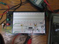
i will do the changes as suggested by you . I have populated 1/2 of parts on the breadboard this morning.
To increase the idle current through the series resistor, i am contemplating placing a 1K R from + to ground at the output of the shunt.
Any comments ?
Can you estimate the current through the j310 ?
My electronic knowledge is very basic.
much appreciated.
regards
kp93300 .
I breadboarded one today too. ")
I think you are OK without any extra load on the shunt. It appears that the circuit AC couples the op amp to the transistor, so only the noise or other signal riding on the input DC gets shunted, regardless of the current draw of your load. The more load current though, the more drop across the shunt resistor of course, and hence some loss of voltage level regulation.
That is an LME49740 in the picture, the quad version of the LME49710, using 1/4 of it. The math almost matched reality - I had to go up to a 9.1k bias resistor instead of the 8.45k to get 18.8mA shunt current through the 220 ohm resistor. I haven't tried it with a BD139 yet, I'll do that this weekend. That 2n4401 definitely needs a heat sink at the 400mW - starts to slowly drift without.
If you are learning electronics you might have some fun figuring out the DC bias point of the op amp. At DC the caps are all opens, of course, so no DC can flow that way (in reality there is a tiny leakage current, but ignore that now). Then apply the two laws of op amps: (1) the input voltages are forced to be the same by the feedback, and (2) the inputs draw no current, meaning all currents at each input node sum to zero. The inputs really do draw a small bias current and have offset voltage, but ignore those here.
The 10K voltage divider applies half the incoming voltage to the non inverting input - 12V. Any AC riding on the DC, like 2mV of noise, also gets cut in half. By (1) the non-inverting input must also be at 12V. With the caps open the only path to ground for current is through the 300K resistor (I've built it up here with the 300K and the 0.05R shunt). Since there is 19mA through the transistor emitter resistor, the 300k resistor returns to (0.019)(15) = 0.28V. Assume here the emitter current is much larger than the current through the 300k. So the current in the 300K resistor is (12V - 0.28V)/300k = 39uA.
Since no current can go into or out of the inverting op amp input by (2), all that current must come through the 47K+1K resistors to the op amp output. That gives a drop across those resistors of (39uA)(48k) = 1.88V. Now add that to the 12V at the inverting input and you get the op amp output DC bias point, (12V + 1.88) = 13.88v.
On your J310 - from the datasheet is looks like the maximum drain current of that jfet is 24mA - 50mA. so your circuit would pull no more than that. You are probably OK with the shunt as it is.
You may want to take a look at this review article of the Wenzel shunt:
Reducing Power Supply Ripple and Noise
They were not impressed. The conclusion: "the attenuation at the null point changes over 30 dB for a 3% change. Since the same change could easily occur with normal temperature variations, we conclude this circuit is too unstable to be very useful."
I think you are OK without any extra load on the shunt. It appears that the circuit AC couples the op amp to the transistor, so only the noise or other signal riding on the input DC gets shunted, regardless of the current draw of your load. The more load current though, the more drop across the shunt resistor of course, and hence some loss of voltage level regulation.
That is an LME49740 in the picture, the quad version of the LME49710, using 1/4 of it. The math almost matched reality - I had to go up to a 9.1k bias resistor instead of the 8.45k to get 18.8mA shunt current through the 220 ohm resistor. I haven't tried it with a BD139 yet, I'll do that this weekend. That 2n4401 definitely needs a heat sink at the 400mW - starts to slowly drift without.
If you are learning electronics you might have some fun figuring out the DC bias point of the op amp.
At DC the caps are all opens, of course, so no DC can flow that way (in reality there is a tiny leakage current, but ignore that now). Then apply the two laws of op amps: (1) the input voltages are forced to be the same by the feedback, and (2) the inputs draw no current, meaning all currents at each input node sum to zero. The inputs really do draw a small bias current and have offset voltage, but ignore those here.The 10K voltage divider applies half the incoming voltage to the non inverting input - 12V. Any AC riding on the DC, like 2mV of noise, also gets cut in half. By (1) the non-inverting input must also be at 12V. With the caps open the only path to ground for current is through the 300K resistor (I've built it up here with the 300K and the 0.05R shunt). Since there is 19mA through the transistor emitter resistor, the 300k resistor returns to (0.019)(15) = 0.28V. Assume here the emitter current is much larger than the current through the 300k. So the current in the 300K resistor is (12V - 0.28V)/300k = 39uA.
Since no current can go into or out of the inverting op amp input by (2), all that current must come through the 47K+1K resistors to the op amp output. That gives a drop across those resistors of (39uA)(48k) = 1.88V. Now add that to the 12V at the inverting input and you get the op amp output DC bias point, (12V + 1.88) = 13.88v.
On your J310 - from the datasheet is looks like the maximum drain current of that jfet is 24mA - 50mA. so your circuit would pull no more than that. You are probably OK with the shunt as it is.
You may want to take a look at this review article of the Wenzel shunt:
Reducing Power Supply Ripple and Noise
They were not impressed. The conclusion: "the attenuation at the null point changes over 30 dB for a 3% change. Since the same change could easily occur with normal temperature variations, we conclude this circuit is too unstable to be very useful."
Attachments
Thanks agdr for the explanation.
I wish I have this sort of knowledge so that I can build more intelligently.
I finish the circuit with 0.1 series resistor and 150 K as mentioned above.
I use bd139 and Lm833.
I test it with 23 V and noted that the 1/4 w 220R runs hot . The BD is ok with a smallish heatsink. .
I am planning to use the shunt with a 28 V dc input rather than 24 V dc input .
The review for this shunt is not favourable but I am going to test it anyway.
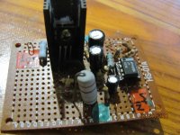
I evaluate the previous Finesse shunt again and the improvement is definitive and across all the freq range with better separation of instrument and wider soundstage.
The attached file is the Finesse shunt completed today. You must excuse me for the rather untidy handiwork.
regards
kp 93300
I wish I have this sort of knowledge so that I can build more intelligently.
I finish the circuit with 0.1 series resistor and 150 K as mentioned above.
I use bd139 and Lm833.
I test it with 23 V and noted that the 1/4 w 220R runs hot . The BD is ok with a smallish heatsink. .
I am planning to use the shunt with a 28 V dc input rather than 24 V dc input .
The review for this shunt is not favourable but I am going to test it anyway.
I evaluate the previous Finesse shunt again and the improvement is definitive and across all the freq range with better separation of instrument and wider soundstage.
The attached file is the Finesse shunt completed today. You must excuse me for the rather untidy handiwork.
regards
kp 93300
Attachments
Hi, more experienced diyer,
Please see the attached images.
The circuit is from Wenzel associates .
Finesse Voltage Regulator Noise!
I build the shunt hoping to clean up a 24 V dc supply for my pre.
The 2n 4401 becomes too hot to touch after 5 minutes. However, there is no problem if i powered with 12 V dc.
I have checked the spec of 2n 4401 and is within operating range.
What are the values to change to prevent overheating of the 2n 4401 ?
thanks
kp93300
Excuse me, but the circuit makes abolutely no sense to me.
There is no feedback loop which would reduce noise, the topology 'could' work as a well matched error feedforward, but it doesn't.
Do I miss something?? or do you?
Edit: I missed
the transconductance is actually trimmed to nullify over a series resistor. So it actually is feedforward error correction.
Last edited:
I test the build in the pre and this are the following parameters
Input 27. 4 V
V across 220 R is 12.3 V
V across 15 R is 0.884V
V at the Vout of the op amp is about 38 V ac
I use 0.1 R series resistor and 150 K feedback at the Bd 136
Are these values within expected limits ?
The deep soundstage seems deeper and wider .. The decay from piano and guitar is improved
I noted the 2 W 220 R runs really hot and Too hot to touch after 10 minutes. Anyway, i leave it on for 45 minutes and still ok.
I wish I have a scope to check.
I will replace a 220R with a 5W .
Thanks you all.
kp93300
Last edited:
Whoops - I didn't notice the reply in this thread until now.
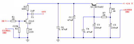
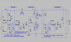
Here is a schematic of the BD139 version. The voltages listed in blue I measured right off the actual circuit, while the currents I've calculated from the voltages. I used an LME49860 just since I had it and it goes up to 44V for supply voltage. 8.2k turned out to be the right value here in place of the 4300R in the original Wenzel circuit to produce the same shunt current. Try the 8.2k resistor in that position and see if it fixes some problems.
That 220R resistor should only have about 5V across it in steady state bias . That works out to (5^2)/220 = 113mW = 0.113W. At 12.3V that is 690mW and 56mA through the shunt. Your shunt is turning on too hard for some reason.
If you are feeding 27.4V to the shunt it should not be possible to exceed that voltage anywhere in this circuit. I'm not sure where the 38VAC at the op amp output would come from. The absolute maximum supply voltage on the LM833 is 36 volts. Maybe a error with your test meter?
I hope this helps!
EDIT! I think that I just spotted the problem. A BD136 is a PNP transistor. That may have just been a typo, but if not you want the BD139 which is the NPN. The one I mentioned above is a "BD139-16". That is the "high gain/hfe" version of the BD139, with the Fairchild part anyway, which has a minimum hFE of 100. Your supplier may have got the request a bit mixed up and gave you a BD136 instead of a BD139-16. On the Fairchild datasheet they have the -16 in a grid under the main set of AC parameters.
Attachments
Last edited:
How to trim the simple shunt ?
Hi guys,
I built one of the simple 2N4401 shunts to use with a tcxo.
I have it working but my dmm and scope don't go low enough (1mV) for me to trim it correctly. So I have measured the voltage drop across the 15 ohm resistor (0.21V) and trimmed the emitter resistor (10 ohm with a 50 ohm trimmer in parallel) so it also has 0.21V across it. Does this seem the right way to do it ?
I can't seem to get the picture to show....oh well.
http://www.flickr.com/photos/30303503@N06/5560821578/
An externally hosted image should be here but it was not working when we last tested it.
Last edited:
An externally hosted image should be here but it was not working when we last tested it.
Hi agdr,
Your help is much appreciated.
I check the the build this afternoon and notice some error that i correct. The measurement is very close to what you posted.
I am using BD 139 .
Well, it sound more refined and even better layering and extends way outside the speaker.
HI Klipschkid,
I also do not know much to answer your questions but I build 2 of this to power the TDA1545 and even without trimming i hear an improvement. I will follow what you do if somebody can confirm.
please post your findings.
regards kp93300
Hi Kp,
It's great to see you trying this out too !
I bought one of these kits from Ebay ecause it uses a pre-reg design :
Low Jitter clock to upgrade Cd player Usb to spdif dac on eBay (end time 29-Mar-11 15:51:53 BST)
But after building it I found the noise was quite high so I added snubbers on the bridge rectifier, fitted a larger smoothing cap, added a couple of caps in beween the regulators, and a couple more from adj to gnd, all to reduce noise. This halved it but still quite noisy.
So I built the simple shunt to reduce noise and adjusted the reg output so there was 5.00V under load at the tcxo.
It's all good, but I'd like to trim it. My brain tells me that if there is a .21V drop across the series resistor, there must be the same drop to gnd, because that means the right current is flowing.
So I think I need to trim it so the drop from the base of the 2N4401 to gnd is the same as the drop across the series 15 ohm resistor.
If anyone can help with this I'd be very grateful !
Thanks !
Tom
It's great to see you trying this out too !
I bought one of these kits from Ebay ecause it uses a pre-reg design :
Low Jitter clock to upgrade Cd player Usb to spdif dac on eBay (end time 29-Mar-11 15:51:53 BST)
But after building it I found the noise was quite high so I added snubbers on the bridge rectifier, fitted a larger smoothing cap, added a couple of caps in beween the regulators, and a couple more from adj to gnd, all to reduce noise. This halved it but still quite noisy.
An externally hosted image should be here but it was not working when we last tested it.
So I built the simple shunt to reduce noise and adjusted the reg output so there was 5.00V under load at the tcxo.
It's all good, but I'd like to trim it. My brain tells me that if there is a .21V drop across the series resistor, there must be the same drop to gnd, because that means the right current is flowing.
So I think I need to trim it so the drop from the base of the 2N4401 to gnd is the same as the drop across the series 15 ohm resistor.
If anyone can help with this I'd be very grateful !
Thanks !
Tom
Here is something to try. I believe there is oscilloscope software for PC sound cards out there, if you don't have a scope. I've never used any, so don't have a recommend, but I believe I've seen mention of it in the software tools forum here. A search there would probably turn up something. Also if your DMM has a fairly wideband frequency rating on the AC measurement range and a 0.1mV resolution that might do the job too. It looks like the Fluke 177 is rated from 10hz to 50kHz, if I'm reading that right.
But in either case you would need to (low noise) amplify the remaining noise signal, after the shunt, to get it up to the level the DMM or soft scope can use. Then you should be able to see the circuit "null" when you adjusted something like a 950R reistor in series with a 100R trimmer to replace the 1k fixed from non-inverting to ground.
You can make an amp like that by using the other (unused) half of that LM833 and wiring it up as below - similar amp circuit to the main shunt. That gives you a unity gain follower at DC (caps open) with output of 12V, then a non-inverting gain up to 150 as the impedance of the 100uF caps go down with frequency. The input 10K voltage divider cuts the noise signal in half (and dc biases the op amp amplifier in the middle of the rails since it is not a rail-to-rail op amp), then the amplifier increases that by up to 150, giving you a maximum total gain of 75. So if you had, say, 50uV of noise left after the shunt that would be (50uV)(75) = 3.75mV out, probably enough for your DMM or sound card scope to "see". Just turn the trimmer and adjust for a null. Even though the op amp will add some noise itself to the measurement signal, it won't matter since you a just looking for a null here, not an accurate absolute value.
I would say that ears are the final inspector with the Wenzel circuit. If it sounds good, great! I'm not sure I totally agree with some of that white paper's concerns. There is some negative feedback going on in the circuit. With the base bias resistor taken off the collector of the transistor, after the 220R resistor, that should give you some dc compensation from the bias point if thermal increases happen in the emitter resistor (transistor current up, 220R drop up, base voltage down, transistor current back down), which was one concern in that paper. The design also gives you ac feedback from collector to base. From their webpage the Wenzel company appears to have been around 30 years in Austin, TX selling low noise RF oscillators and such to military and government clients. Sounds like they know what they are doing, at least with RF gear. I wouldn't write the Wenzel circuit off without seeing some more in-depth analysis.
But in either case you would need to (low noise) amplify the remaining noise signal, after the shunt, to get it up to the level the DMM or soft scope can use. Then you should be able to see the circuit "null" when you adjusted something like a 950R reistor in series with a 100R trimmer to replace the 1k fixed from non-inverting to ground.
You can make an amp like that by using the other (unused) half of that LM833 and wiring it up as below - similar amp circuit to the main shunt. That gives you a unity gain follower at DC (caps open) with output of 12V, then a non-inverting gain up to 150 as the impedance of the 100uF caps go down with frequency. The input 10K voltage divider cuts the noise signal in half (and dc biases the op amp amplifier in the middle of the rails since it is not a rail-to-rail op amp), then the amplifier increases that by up to 150, giving you a maximum total gain of 75. So if you had, say, 50uV of noise left after the shunt that would be (50uV)(75) = 3.75mV out, probably enough for your DMM or sound card scope to "see". Just turn the trimmer and adjust for a null.
Even though the op amp will add some noise itself to the measurement signal, it won't matter since you a just looking for a null here, not an accurate absolute value.I would say that ears are the final inspector with the Wenzel circuit.
If it sounds good, great! I'm not sure I totally agree with some of that white paper's concerns. There is some negative feedback going on in the circuit. With the base bias resistor taken off the collector of the transistor, after the 220R resistor, that should give you some dc compensation from the bias point if thermal increases happen in the emitter resistor (transistor current up, 220R drop up, base voltage down, transistor current back down), which was one concern in that paper. The design also gives you ac feedback from collector to base. From their webpage the Wenzel company appears to have been around 30 years in Austin, TX selling low noise RF oscillators and such to military and government clients. Sounds like they know what they are doing, at least with RF gear. I wouldn't write the Wenzel circuit off without seeing some more in-depth analysis. Attachments
Last edited:
- Status
- This old topic is closed. If you want to reopen this topic, contact a moderator using the "Report Post" button.
- Home
- Amplifiers
- Power Supplies
- wenzel associates finesse shunt