edit: (probably not as its voltage out, but there will be a minimum load impedance)
edit 2: yep, OK it has a minimum load of 1KΩ measured differentially balanced, so you'll need to check. also if driving capacitive loads (cables, your poweramp input perhaps) you need to buffer the output with some resistance between the DAC chip and the capacitance; at a minimum; so if you wont use a buffer/filter, perhaps try adding some smallish resistance between the dac and the RCA, i'll check out some values. maybe up to 10K, but probably 3.3-5k connected from each output->GND will do
edit 2: yep, OK it has a minimum load of 1KΩ measured differentially balanced, so you'll need to check. also if driving capacitive loads (cables, your poweramp input perhaps) you need to buffer the output with some resistance between the DAC chip and the capacitance; at a minimum; so if you wont use a buffer/filter, perhaps try adding some smallish resistance between the dac and the RCA, i'll check out some values. maybe up to 10K, but probably 3.3-5k connected from each output->GND will do
Last edited:
I've not used the AK4399 but the AK4393/5/6 work very well with a line output transformer. This balances the load, allows SE or balanced output as required and provides gentle filtering of ultrasonics. I've tried several transformers (Sowter, old Jensen, basic Lundahl etc.) but to my ears the best bang to the buck for the AK4396 was the Tamura TK-1
2 pcs Tamura TAMRADIO TK-1 600? CT : 600? audio transformer | eBay
No doubt the better modern transformers will better the TK-1s, but these are great for the money.
2 pcs Tamura TAMRADIO TK-1 600? CT : 600? audio transformer | eBay
No doubt the better modern transformers will better the TK-1s, but these are great for the money.
no worries peterma, dont take it the wrong way and dont stop experimenting or telling others about the experiments. but if you dont have technical information/measurements of the procedures, best not to guess, or proclaim technical/semi-technical improvements, thats where the problems begin and where the majority of arguments originate.
yeah even if its not immediately audible, protecting the DAC output from driving the cables and their complex impedance directly, will certainly make it more well behaved and it will also protect the DAC from having noise injected directly into it.
do remember that it will probably lower the amplitude a bit, so you may need to turn the volume on the amps up a touch to match the previous output. make sure to do that, or you may mistake lower level for less dynamic etc.
i found this on ebay:
Assembled AK4399 PCM2706 WM8805 OPA627AU Audio DAC Boad include USB Card | eBay
its same weiliang dac9 and include usb modul pcm2706, but price cheaper weiliang dac9, anyone tried it ?
Assembled AK4399 PCM2706 WM8805 OPA627AU Audio DAC Boad include USB Card | eBay
its same weiliang dac9 and include usb modul pcm2706, but price cheaper weiliang dac9, anyone tried it ?
I'm late?
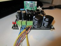
I've bought this DAC last month but I was waiting to open a thread because I wanted to publish an upgrade BOM like I did for the AK4396 DAC.
Well, someone started earlier...")
BTW
This DAC sound great as it is, I can't see any fake parts (including supplied AD797), some LT regulators are used, though, and some parts are useless or way sub-par..
I agree that other opamps sound better though (OPA827, for example) but it was expected, AD797 needs a dedicated design to sound best.
One strange thing is that the supplied gold/black Silmics II sound (way) better that white/brown ones you can buy from Mouser/Digikey/PCX, etc.
If those are fakes I want fakes everytime!!
BTW the first parts mods are, as usual, on the LPF (I''m not a fan of direct out mods):
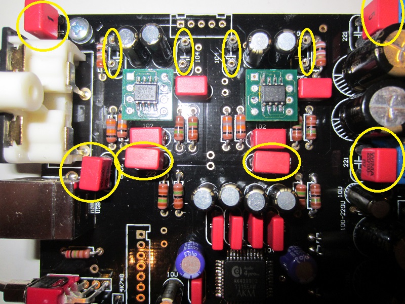
So, get rid of all 220pF PFR5 and use Wima FKP2 or Amtrans AMCH instead (fuller and more deteailed sound).
Remove all MKS2 bypasses of Silmics (more natural reverbs and less fatigue),
Replace the 2.7nF green EROs with Wima FKP2/Amtrans 2200pF.
After that replace the Samwha smoothing caps with Panasonic TS-HAs, same value:

This has a HUGE impact of sound, fuller and more detailed, those Samwhas are the worst quality parts in the kit.
If possible replace the 2 1000uF Panasonic FM with Elna RJHs you'll have sweeter HF and a more balanced timbre.
You can also use Nichicon FWs, better than FMs but not as good as RJHs.
For an overkill result you can swap the Samwhas with Mundorf AGs but, while they're an improvement over TS-HAs, the cost/benefit ratio is not that high.
In every case remove the bypasses of the smoothing caps.
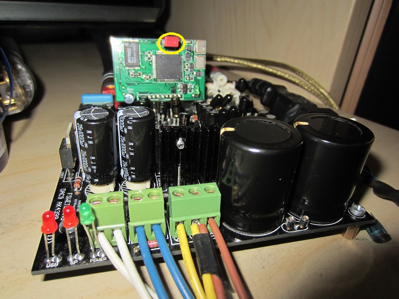
If you have the CM6631 USB option replace the blue box cap with Wima MKP2, you'll gain a fuller and more refined sound.
I've noted that using USB sound is not as full as using SPDIF.
Last the DAC decoupling... from my experience on the MINI2496 I was expecting great results here but the vendor selections is quite good.
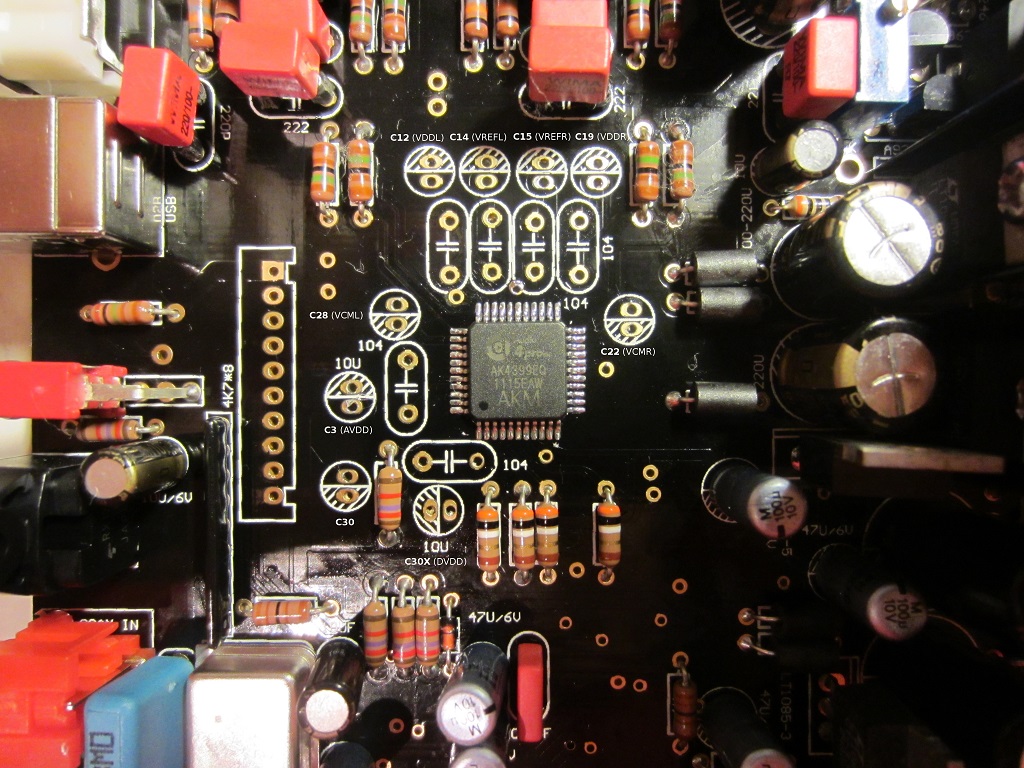
I've tried various OSCONS (Nichicons, Fujitsu, Sanyo) and plain capacitors and the supplied Sanyo for C30X sound really good, beaten only by Black Gate STD.
On C22/C28 the supplied oscons sound remarkably good but Black/gold Silmics II or BGs sound best.
On other positions the supplied Silmics are a really good choice, simply remove all MKS2 bypasses.
In general where an OSCON is used a bypass is very bad idea, remove it as well.
Having brand new caps with long leads would be a good idea to solder elcos nearer to DAC pins using the bypasses positions.
This is what I've discovered so far, subject to change and an ongoing test.
I've bought this DAC last month but I was waiting to open a thread because I wanted to publish an upgrade BOM like I did for the AK4396 DAC.
Well, someone started earlier...
BTW
This DAC sound great as it is, I can't see any fake parts (including supplied AD797), some LT regulators are used, though, and some parts are useless or way sub-par..
I agree that other opamps sound better though (OPA827, for example) but it was expected, AD797 needs a dedicated design to sound best.
One strange thing is that the supplied gold/black Silmics II sound (way) better that white/brown ones you can buy from Mouser/Digikey/PCX, etc.
If those are fakes I want fakes everytime!!
BTW the first parts mods are, as usual, on the LPF (I''m not a fan of direct out mods):
So, get rid of all 220pF PFR5 and use Wima FKP2 or Amtrans AMCH instead (fuller and more deteailed sound).
Remove all MKS2 bypasses of Silmics (more natural reverbs and less fatigue),
Replace the 2.7nF green EROs with Wima FKP2/Amtrans 2200pF.
After that replace the Samwha smoothing caps with Panasonic TS-HAs, same value:
This has a HUGE impact of sound, fuller and more detailed, those Samwhas are the worst quality parts in the kit.
If possible replace the 2 1000uF Panasonic FM with Elna RJHs you'll have sweeter HF and a more balanced timbre.
You can also use Nichicon FWs, better than FMs but not as good as RJHs.
For an overkill result you can swap the Samwhas with Mundorf AGs but, while they're an improvement over TS-HAs, the cost/benefit ratio is not that high.
In every case remove the bypasses of the smoothing caps.
If you have the CM6631 USB option replace the blue box cap with Wima MKP2, you'll gain a fuller and more refined sound.
I've noted that using USB sound is not as full as using SPDIF.
Last the DAC decoupling... from my experience on the MINI2496 I was expecting great results here but the vendor selections is quite good.
I've tried various OSCONS (Nichicons, Fujitsu, Sanyo) and plain capacitors and the supplied Sanyo for C30X sound really good, beaten only by Black Gate STD.
On C22/C28 the supplied oscons sound remarkably good but Black/gold Silmics II or BGs sound best.
On other positions the supplied Silmics are a really good choice, simply remove all MKS2 bypasses.
In general where an OSCON is used a bypass is very bad idea, remove it as well.
Having brand new caps with long leads would be a good idea to solder elcos nearer to DAC pins using the bypasses positions.
This is what I've discovered so far, subject to change and an ongoing test.
Attachments


Last edited:
haha elcos with long leads as HF bypass caps for the DAC?
interesting advice …
bypass caps need to be low inductance and low impedance at high frequency, elcos with (or without) long leads ... are neither.
that being said, even the bypass positions arent really close enough to be useful.
but I shall leave you to your expert, reality bending instruction.
interesting advice …
bypass caps need to be low inductance and low impedance at high frequency, elcos with (or without) long leads ... are neither.
that being said, even the bypass positions arent really close enough to be useful.
but I shall leave you to your expert, reality bending instruction.
Last edited:
haha elcos with long leads as HF bypass caps for the DAC?
interesting advice …
haha, maybe you should try to understand, first....
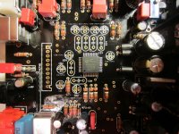
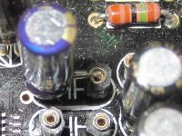
film bypasses positions are much nearer to the chip, so what I was suggesting is to use them for elcos.
But you can't with existing elcos, trimmed for 2,5mm lead spacing... so you must use new elcos so that you can trim leads for 5mm lead spacing, possibly with the end of cap on chip right on pad and the other (to ground) longer.
I'll attach a pic, it seem needed:
And this makes perfectly sense for OSCONS, where bypasses can lead to resonance problems and are not needed at all, since OSCONs are effective to a much higher frequency than plain elcos.
In my personal experience this makes sense also for normal anaolog PS decoupling, often the 'one for all' 100nF bypass has more drawbacks than advantages.
One question, on analog PS lines of the DAC are high frequency bypasses really needed?
Attachments
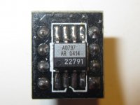
How do you think, does the upgrade opamps from minishow genuine?
My kit come with the AD797, from pic I can't say they're not genuine:
Anyone with different opinion? (and why?)
Attachments
oh I understand perfectly and you just illustrated it perfectly, lead inductance can lead to resonance too... and youve even added some extra inductance with the sockets!! … use a decent regulator and JUST use the bypasses (or calculate correct values for both), the resonance comes from just throwing random/arbitrary value bypass caps at random/arbitrary value parallel electros and not measuring to check for resonance. if your DAC needs large decoupling close to the DAC, there is something wrong with the design and those caps like that are not going to do anything about HF noise/ripple
do the analogue lines need HF bypasses? yes, the noise is all around, from the dac logic itself, from the clock, from the air and from those leads... less than great regulators dont have the best HF rejection either. bypasses should be as physically small and physically close as possible. isolate individual supplies with common mode chokes or CLC filters if you need to share with digital preregs and use a controlled value inductor, rather than unknown with long leads, which just renders them ineffective.
do the analogue lines need HF bypasses? yes, the noise is all around, from the dac logic itself, from the clock, from the air and from those leads... less than great regulators dont have the best HF rejection either. bypasses should be as physically small and physically close as possible. isolate individual supplies with common mode chokes or CLC filters if you need to share with digital preregs and use a controlled value inductor, rather than unknown with long leads, which just renders them ineffective.
Last edited:
oh I understand perfectly and you just illustrated it perfectly, lead inductance can lead to resonance too... and youve even added some extra inductance with the sockets, well done!! …
You understand perfectly... sure.
You were riduculizing my comment as I was recommending using caps with long leads and it was not the case.
Those sockets are here only to try different caps, not to stay...
if your DAC needs large decoupling close to the DAC, there is something wrong with the design and those caps like that are not going to do anything about HF noise/ripple
As you arealdy should know, this is not my design.
I'm only optimizing parts selection for myself and sharing my findings.
If you're not interested, please ignore my posts, unless you have some constructive comments.
yes, I do…
You have used caps with long leads and pinheaders for HF bypass caps and deleted the HF bypass caps, which were already too far away and the wrong type, then you have illustrated a mod using caps with much worse HF and transient performance again and added headers. a couple mm is too long for HF bypass
does constructive mean it must agree with your play the HF bypassing by ear and incorrect assertions?, including you asking if the low noise pins need HF bypassing anyway, which they most certainly DO?
you may not like it, but thats constructive criticism, especially for others to consider and I have explained exactly why, you choose to ignore the reality of the situation, thats fine, but dont try and tell me its not constructive, just because you disagree.
ground pins are usually right next to the supply pins, use the smallest x7r cap (0402 size) soldered directly across the pins. size them correctly to avoid resonance with the electros
Last edited:
does constructive mean it must agree with your play the HF bypassing by ear and incorrect assertions? (...) but dont try and tell me its not constructive, just because you disagree.
I never told so... for a constructive comment I mean one where you explain why you disagree with mine without distorting and ridiculizing what I wrote.
Maybe you can discover that I agree with you more than you think.
It has also to do with a thing called respect...
ground pins are usually right next to the supply pins, use the smallest x7r cap (0402 size) soldered directly across the pins.
I do agree and this would be the MOST effective way to do HF decoupling.
But you don't always need the most effective or you can use other techniques.
Also I do agree that X7R ceramics are pretty good caps for such role, possibly SMD and the lossy polyester caps used by the DAC9 are, in practice, useless (so why not pull them out since they do more harm than good?
).Often small bypasses are used as easy band-aids to cover other design problems (in the PCB layout for example).
size them correctly to avoid resonance with the electros
I wouldn't be so sure about it, a small bypass on a low ESR/ESL caps most of the times lead to resonances...If the elco, like solid polymer ones, are effective 'till tens of megahertz it's easier to leave the bypass out, isn't it?
- Status
- This old topic is closed. If you want to reopen this topic, contact a moderator using the "Report Post" button.
- Home
- Source & Line
- Digital Source
- Weiliang DAC9 with AK4399