Maybe I need to reemphasize that all horn/driver combinations as a "system" will have peaks at low frequencies - even if the "horn" does not.
That's not true. A horn that provides reasonably good acoustic loading will not have peaks its response curve when driven with a compatible driver. There are numerous examples of horn/driver combinations that provide smooth, ripple-free response.
I don't know if yours is capable of that, but from your objections, I would guess not. The SEOS horns have peaks at 1kHz, 2kHz, 4kHz and 7kHz. Where are the peaks in yours?
All of this "response shaping" versus "impedance shaping" is just talking around the issue.
That also is not true. Using filters for impedance compensation is well-understood. Otto Zobel is the first I know to describe them, back in the 1920s or so. Response shaping is completely different, and may be employed even where impedance compensation is not.
Last edited:
Wayne,
While I agree that an impedance correction circuit can flatten the impedance rise or a peak in the impedance curve that is only a part of the picture. Typically as Earl has stated you have a single impedance rise in the bottom of the band due to the device resonance which is often ignored and taken care of by a suitably high crossover point, though this is not a perfect solution as Earl has pointed out as you will still have some in-band ripple and the second source would just be the typical rising rate of most devices impedance curve. This second rate increase can be countered by a conjugate matched tank circuit that will flatten this impedance rise though actually making it perfectly flat doesn't often happen. But neither of these two impedance correction circuits is going to do anything about the normal mass roll-off of a compression driver. This would require a filter with either a shelf or a matching slope to bring up the top end. What would bother you about doing this either passively, difficult to do well, or actively and flattening the FR of the pass-band? I have not brought into the discussion of any resonant behavior in the pass-band due to a mechanical problem with the compression driver as this I have a problem with myself and do not think that an electrical circuit is truly capable of successfully correcting without causing phase and program problems while still leaving the simple mechanical resonance problems that can be excited with or without an electrical signal.
While I agree that an impedance correction circuit can flatten the impedance rise or a peak in the impedance curve that is only a part of the picture. Typically as Earl has stated you have a single impedance rise in the bottom of the band due to the device resonance which is often ignored and taken care of by a suitably high crossover point, though this is not a perfect solution as Earl has pointed out as you will still have some in-band ripple and the second source would just be the typical rising rate of most devices impedance curve. This second rate increase can be countered by a conjugate matched tank circuit that will flatten this impedance rise though actually making it perfectly flat doesn't often happen. But neither of these two impedance correction circuits is going to do anything about the normal mass roll-off of a compression driver. This would require a filter with either a shelf or a matching slope to bring up the top end. What would bother you about doing this either passively, difficult to do well, or actively and flattening the FR of the pass-band? I have not brought into the discussion of any resonant behavior in the pass-band due to a mechanical problem with the compression driver as this I have a problem with myself and do not think that an electrical circuit is truly capable of successfully correcting without causing phase and program problems while still leaving the simple mechanical resonance problems that can be excited with or without an electrical signal.
There are numerous examples of horn/driver combinations that provide smooth, ripple-free response.
Wayne
Show me an example of a horn/compression driver system that has no peaks when there is no electrical modification.
...neither of these two impedance correction circuits is going to do anything about the normal mass roll-off of a compression driver. This would require a filter with either a shelf or a matching slope to bring up the top end. What would bother you about doing this either passively, difficult to do well, or actively and flattening the FR of the pass-band?
Using filters to conjugate mass-rolloff doesn't bother me. You pretty much have to do that for any horn that provides constant directivity but it's a pretty simple first-order slope. There's a little more to it than that, because the response below mass rolloff is generally flat, so the conjugate filter needs a flat region followed by a second region with rising response, to counter where mass-rolloff begins.
What bothers me is using horns that have a lot of ripple, and then smoothing them with response-shaping notch filters. I have never found that approach to be satisfactory.
As for impedance compensation, there are a myriad ways to do it, but sometimes I like having the complex impedance of the horn/driver in the circuit to modify the transfer function in a favorable way. The changing impedance can be expoited to one's advantage. In those cases, I do not try to set load impedance flat, but instead use changing impedance of the load to modify the transfer function. This approach uses fewer parts, and sometimes allows really useful filter functions to be formed, with more complex shape than one would expect from the parts count. But the point still remains, that there is a filter function type that specifically requires a flat "resistive" load. This would be an impedance modification filter, like what was described by Zobel so long ago.
Show me an example of a horn/compression driver system that has no peaks when there is no electrical modification.
Below you'll find a pretty good example. It's a TAD compression driver on one of their radial horns of a decade ago.
You can find lots of other examples like this. I myself used a radial horn for quite some time that was really smooth on-axis and had pretty good horizontals too.
Attachments
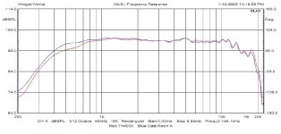
While I might question the details of that system, I'll give you that it might be possible, but it is the exception, not the norm. Most systems will not be over-damped with extremely low cutoffs like that one and those will always exhibit a peak. A peak which is easily and effectively flattened with a LRC circuit.
I think this is where we meet in the middle. I tend to agree that, especially for conical horns and waveguides, it is often useful to damp the lowest peak with the crossover. Conical horns and waveguides tend to have poor acoustic loading at low frequencies so you have to live with that to get their inherent benefits in other areas, i.e. directivity, wavefront propogation, etc.
But just like I said in the Uniform Directivity thread, I wouldn't throw the baby out with the bathwater. I'm not willing to trade smooth response and accept a lot of ripple. I'm ok with one resonant mode, down in the crosover region where I can damp it naturally. But I'm not ok with three or four of them, all the way up the band. That's the way some of the old prosound CD horns act, and they sound nasty even when equalized flat.
But just like I said in the Uniform Directivity thread, I wouldn't throw the baby out with the bathwater. I'm not willing to trade smooth response and accept a lot of ripple. I'm ok with one resonant mode, down in the crosover region where I can damp it naturally. But I'm not ok with three or four of them, all the way up the band. That's the way some of the old prosound CD horns act, and they sound nasty even when equalized flat.
I think this is where we meet in the middle. I tend to agree that, especially for conical horns and waveguides, it is often useful to damp the lowest peak with the crossover. Conical horns and waveguides tend to have poor acoustic loading at low frequencies so you have to live with that to get their inherent benefits in other areas, i.e. directivity, wavefront propogation, etc.
But just like I said in the Uniform Directivity thread, I wouldn't throw the baby out with the bathwater. I'm not willing to trade smooth response and accept a lot of ripple. I'm ok with one resonant mode, down in the crosover region where I can damp it naturally. But I'm not ok with three or four of them, all the way up the band. That's the way some of the old prosound CD horns act, and they sound nasty even when equalized flat.
When I said "damp it naturally", I meant by virtue of the crossover. In the crossover region, the crossover filters naturally have a large degree of influence on the system response. I set the damping of the crossover filter using a pair of resistors. It's not a notch filter or a Zobel, but it does provide specific damping, which is set using the values of the resistors. These two resistors combined with the load impedance actually form a Pi filter, which is not related to my loudspeaker brand name but is a happy coincidence.
I still am not in agreement, but I am tired of arguing with you.
I usually stop when there is nothing to be gained by convincing the person I'm debating of my position.
Your product speaks for itself.
Pi networks are used for impedance matching, among other things. Yes, they can be used as power supply filters too.
Well, sure, adapters aren't necessarily bad, provided they match the driver and horn well. That's a fairly critical junction. And this also brings us back full circle, which is to suggest that when swapping horns and drivers around, you may need to modify the crossover each time.
Earlier in this thread, someone said they thought their waveguide/horn was harsh, and I pointed out that if the one they were using didn't have notch filters at 2kHz and 4kHz, it would sound bad. That particular waveguide has large peaks at 1kHz, 2kHz and 4kHz, so if you crossover above 1kHz, you will reduce the first peak but you still have 5dB peaks at 2kHz and 4kHz, and most people use notch filters to smooth them out.
Then we went down another road, a discussion on whether or not using notch filters is good enough, or whether it was a compromise for some waveguide/horns, a necessary evil. I personally would prefer the smoother device, for all the reasons I mentioned in this thread.
But whether or not you agree with that, it is probably enough to say that some horns have ripple, others don't. And adapters sometimes change the response too. So when swapping horns and drivers, it is probably best to look at the crossover, to make sure it is compatible with your horn/driver selection.
OK, so wave guide adapters are not nec bad...........
Well, sure, adapters aren't necessarily bad, provided they match the driver and horn well. That's a fairly critical junction. And this also brings us back full circle, which is to suggest that when swapping horns and drivers around, you may need to modify the crossover each time.
Earlier in this thread, someone said they thought their waveguide/horn was harsh, and I pointed out that if the one they were using didn't have notch filters at 2kHz and 4kHz, it would sound bad. That particular waveguide has large peaks at 1kHz, 2kHz and 4kHz, so if you crossover above 1kHz, you will reduce the first peak but you still have 5dB peaks at 2kHz and 4kHz, and most people use notch filters to smooth them out.
Then we went down another road, a discussion on whether or not using notch filters is good enough, or whether it was a compromise for some waveguide/horns, a necessary evil. I personally would prefer the smoother device, for all the reasons I mentioned in this thread.
But whether or not you agree with that, it is probably enough to say that some horns have ripple, others don't. And adapters sometimes change the response too. So when swapping horns and drivers, it is probably best to look at the crossover, to make sure it is compatible with your horn/driver selection.
")
Omholt
You are asking this question of the designer? What kind of answer do you expect?
Wayne - a lot of the problem that I have with what you are saying is that you do not use standard terminology. to me putting in a HP filter to bring down a resonance is not "damping it" - it is response shaping.
If I could paraphrase what I think you are trying to say; You do not believe that horns should have resonances and as such using resonant circuits to "tame" them is not a good idea. If that is what you are saying then I agree with you, but I would note that your objection to the use of LRC circuits here is a secondary issue, the issue is having acoustic resonances and diffractions in the horn in the first place. Electrical means are not usually very effective at internal acoustic problems, so, in general, while they can be of some use, its better to just avoid them with proper horn design.
If, as is virtually guaranteed with a driver like a DE250, there is a peak (or two) caused by the driver resonance then an LRC circuit is very effective at controlling this issue because it is a lumped parameter mechanical resonance. Proper implementation does apply!
I think that this is your position, (I hope, because otherwise we are back into disagreement), but it took me some time to sort it out.
Last edited:
I think part of the problem may be that my vocabulary comes from an electronics perspective whereas yours comes from an acoustics perspective. One of my best friends is a mechanical engineer, and we find some differences in our "language" too, but I've known him so long I've adopted some of his words and he's adopted some of mine. The physics is all the same, so the basic concepts are too. Likewise, most of our words are the same, but some aren't. Mass/spring/damping and inductance/capacitance/resistance, things like that. To tell the truth I think this kind of "cross-pollination" is extremely useful.
Part of my problem with using notch filters comes from the fact that I know parameters shift. There are unit-to-unit inconsistencies and there are thermal shifts. I can get two compression drivers from the same manufacturer, same model, and find different resonant peaks in each. The peaks vary in amplitude and sometimes slightly in frequency too. And as I demonstrated, there are thermal shifts as well. So I use a different strategy, one that isn't as sensitive to parameter shifts. But if you feel that you can lock in the peaks with a notch filter, I'm OK with that. It's probably going to be close, even with parameter shifts moving the target around. As you've said, that's a secondary issue.
The main problem is what causes the ripple in the first place. When I see three or four 5dB peaks through the passband, I'm not going to even consider using a horn like that, even with EQ. So you're exactly right, my main issue is having acoustic resonances and diffractions in the horn in the first place. I agree with you that electrical filters are not usually very effective at solving internal acoustic problems, so, in general, while they can be of some use, its better to just avoid them with proper horn design.
Last edited:
IThe main problem is what causes the ripple in the first place. When I see three or four 5dB peaks through the passband, I'm not going to even consider using a horn like that, even with EQ. So you're exactly right, my main issue is having acoustic resonances and diffractions in the horn in the first place.
Then we are on the same page.
I have seen an issue with manufacturers stability of parameters, but not so much parameter shifts with temperature or age. I test every speaker that I make so I always catch these shifts.
Usually they are shifts rather than random. I suspect that they change a part and then they stay with that new part. The random variations are usually negligible but I have seen permanent shifts that require me to redo the crossover. A real PITA.
- Status
- This old topic is closed. If you want to reopen this topic, contact a moderator using the "Report Post" button.
- Home
- Loudspeakers
- Multi-Way
- Waveguide adapters bad idea?