So, anyways, I see Roadbagger already has AX7's on the bottom, and AV7's on top.
This mismatch is a very good if you are driving a grid into A2 that needs pullup grunt
more than pulldown.
But this same mismatch of slew capability could behave very weird if driving Schaded
FET (Translate "Original Zen" for Zenmod) Triode emulator with a big capactive gate,
Schade (fake Mu feedback from the plate) prefers driven fed from a fixed symmetrical
impedance. Symmetry of slew capability into the next stage can be put to advantage
in such cases (and others), and is not an option to be dismissed lightly!
But lets take SRPP one step further, replacing our top device with a BJT "ring of two"
or BJT+MOSFET "Aleph" style current source. Basically a fake depletion mode device
with very high transconductance follows the voltage of the lower, plus a fixed voltage
offset. The SRPP resistor sets the quiescent current, nothing changed about that...
Load tapped up the top of SRPP resistor, this drives nothing like a real tube anymore.
You gots waaay too much pullup, and still no better pulldown. At the bottom end of
the SRPP resistor, behavior dumbs down to a simple CCS. And here, the triode's plate
gets no power steering assist whatsoever...
But right in the middle (assuming the top follower impedance is pretty near zero),
you got this magic node where you get exactly the same assist as-if you had
another virtual Triode in parallel. Even if the device above isn't a triode, it now
forces itself to become one! But since it must fake this from the other side of
push-pull, its actual behavior is not that of a follower, nor is it complimentary,
but that of a true anti-complement. An Anti-Triode emulator...
A vacuum triode need not be anywhere present to make productive abuse of
a circuit with this behavior (again, see Aleph if anyone doubts). Sorry all the
Nelson Pass ref's. Not one to be accused of following the Curl Camarilla, I try
to translate into Zenmod-eese for the as-yet Anti-Triode challenged...
Same thing only different. Other side of the sand/glass curtain. And all that...
Tar and feathers are the only crucial components.
Last edited:

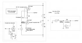
Lemme see if I can dumb it down to a picture...
R1 and R2 would be approximately the same.
This should drive the next stage more like a pair
of 12AX7 in SE parallel would. Not as-if push pull
or SRPP... This is how an anti-compliment works!
Insultramentary my dear Watson...
Abused MJE350 to mismatchify the upper device.
Without it, the "midpoint" might have been hidden
inside the upper Triode's cathode resistance where
we can't easily connect.
Any circuit that acts like a depletion mode will do.
More then one way to skin a cat...
Attachments
Last edited:
And regarding AV7's atop AX7's, does this achieve anything stacked AX7 could not?
I mean, you are having to cut back bias current on the AV7 to the limits of the AX.
If you can't slew down any better for it, does it "lower the impedance" or anything
else??
Even with theoretically infinite Gm above, you can't symmetrically slew any better
than 2x what the lower tube alone can do. And makes no sense to chose any "help"
ratio bigger than 2:1, due the limit of pulldown current. Your Anti-Triode help ratio
is high as the SRPP resistor vs cathode follower resistance allows, but is it REALLY
able to give the help you have asked of it, or already over the 2x hedge and into
the la-la-land of asymmetrical impedance?
But you might could fix either situation by paralleling a CCS with the lower triode.
But then, would we lose our minds and want that current source to become yet
another parallel helper too??? The Auntie of Anti is another emulator... Etc etc...
Where does it all end???
And what of the SRPP drive totems in the WSFB??? What is thier "help" ratio?
Are they driving anything (like a grid in A2) that wants or needs the asymmetry?
If no, then why tap the top end of the SRPP resistor? Was that the best tap
point you could possibly have chosen? I'm not saying for sure it isn't, just that
its maybe worth asking the question.
Last edited:
And before pointing out the fact I've also tapped the top end in my Differential
White Cathode Follower. That actually was about as close to the middle of the
SRPP resistance (counting the cathode) as I could get. So sometimes the top
is the middle, or sometimes close enough, but not always...
Abusing high Gm on top takes a lot of the mystery out of where the middle lies...
White Cathode Follower. That actually was about as close to the middle of the
SRPP resistance (counting the cathode) as I could get. So sometimes the top
is the middle, or sometimes close enough, but not always...
Abusing high Gm on top takes a lot of the mystery out of where the middle lies...
Last edited:
Maybe less coffee would help............
Rfeedback and Output should both perhaps be tapped at the SRPP midpoint?
This would yeild the highest possible slew rate that could still be symmetrical.
Where within the SRPP resistor is this midpoint? Don't rightly know the cathode
follower resistance of an AV7 off the top of my head...
The real difference is when driving a challenging load. An SRPP with symmetry
of slew might only attenuate the signal. An SRPP without slew symmetry will
almost certainly distort, and possibly even rectify DC. Maybe you get away
with it because you have loop feedback? Or maybe your load isn't challenging
enough to reveal the issue? But is it really ideal to lean upon a loop to fix an
error that doesn't ever need be created in the first place?
Better to lean upon coffee.
Last edited:
This design provides a low plate load impedance for the dual triode differential stage to the effect of removing the miller feedback to this pair. The following stage is what is normally referred to as a transimpedance amplifier, current in and voltage out. The approximate 2:1 difference in the device Gm of this "op-amp" pair linearizes the stage gain and slaves the Ib of the lower triode allowing some gain modulation of the upper current source. I think you may not see the vast dissimillarity between what you keep referring to, and this circuit. There is little frequency limiting here or distortion overall. The intermod performance here is down near -90 to -100 db. Though I happen to be a proponent of zero feedback amplifier topologies, there are some chains of gain that, when locally Gain confined, maintain transient response linearity indemic to the stage being fed back. "You loose nothing, you gain precision". The only "challenging load" in an amplifier should only be the final transducer commonly referred to as a speaker. That part is far removed from this discussion.
Last edited:
AV7 cathode resistance is like 1/.0061mho=164ohms ???
Plus 2K2 external SRPP resistor gives us 2364ohms...
So, I'm thinking... Split this like 1K2 on the bottom, and 1K on top,
with the load and feedback tapped between. This appears as 600
ohms in series with 40K (SE plate resistance of two parallel AX7's,
one virtual). And the slew capabilities are now symmetrical.
I am aware this level of nitpick is probably silly if the circuit works.
But there are situations where it might not be silly, and you were
already halfway there to having discovered this symmetry of the
assymetrical on your own. Figured I'd nudge you over that edge...
Big gates can be challenging too.
Last edited:
Well............
I ran a few sims with that proposition and the distortion increases about 10 fold. I think there is a significant difference between what you propose to do and what this circuit is doing, and yes, there is always improvement to any circuit, but that approach is not an answer.
I ran a few sims with that proposition and the distortion increases about 10 fold. I think there is a significant difference between what you propose to do and what this circuit is doing, and yes, there is always improvement to any circuit, but that approach is not an answer.
I wouldn't normally have gone for a mere 2:1 Gm difference...
But I'm a little surprised to hear it actually made things worse.
Is my theory totally broken now, or is AV cathode resistance
doing something strange??? Or merely letting the AX7 plate
directly drive half (double apparent Z) of the real load???
What is the load anyways???
But I'm a little surprised to hear it actually made things worse.
Is my theory totally broken now, or is AV cathode resistance
doing something strange??? Or merely letting the AX7 plate
directly drive half (double apparent Z) of the real load???
What is the load anyways???
Nevermind... I may need totally re-evaluate the way I've been
de-rating output impedance in circuits with asymmetrical pull-up
and pull-down impedances. Its not necessarily that the worser
of the two is the weakest link, as I had till now assumed... It
may be that only Iq and Load are critical factors in pull down.
de-rating output impedance in circuits with asymmetrical pull-up
and pull-down impedances. Its not necessarily that the worser
of the two is the weakest link, as I had till now assumed... It
may be that only Iq and Load are critical factors in pull down.
Last edited:
Mmmmmmm........
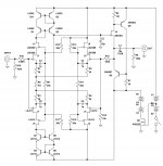
You see, in the Vacuum tube preamp using two triodes as a transimpedance amplifier, (ref: WSF detail), the uppermost triode U3 is not a simple pullup but a dynamic amplifier operating in counterphase with the lower triode U2, there is a voltage modulation across the 2.2 k ohm U3 cathode resistor. U3's cathode current is split between the U1 plate current and the the counterphase U2 current. The upper triode is therefore a gain element acting as a modulatable resistance in the plate of the lower triode. Where this differs from the models you are using is in the use of a third triode U1, feeding current into a summing node. This theme is also used to sum together multiple sources all having a common combinatorial node where all summed plate currents have a complimentary current fed back to to the same node through a single Fbk resistor. The U1 can then be any number of triodes. The resulting DC bias condition can then be removed, without causing any distortion component, through the use of a positive current source into the same node. A single triode feed to the summing node is manageable without cancellation unless a larger feedback resistor was needed, then a cancellation current source would be used to prevent clipping. Dad always said that "all these circuits are the same" "they just keep mixing up all those parts to confuse you, just gotta know which parts go where"

You see, in the Vacuum tube preamp using two triodes as a transimpedance amplifier, (ref: WSF detail), the uppermost triode U3 is not a simple pullup but a dynamic amplifier operating in counterphase with the lower triode U2, there is a voltage modulation across the 2.2 k ohm U3 cathode resistor. U3's cathode current is split between the U1 plate current and the the counterphase U2 current. The upper triode is therefore a gain element acting as a modulatable resistance in the plate of the lower triode. Where this differs from the models you are using is in the use of a third triode U1, feeding current into a summing node. This theme is also used to sum together multiple sources all having a common combinatorial node where all summed plate currents have a complimentary current fed back to to the same node through a single Fbk resistor. The U1 can then be any number of triodes. The resulting DC bias condition can then be removed, without causing any distortion component, through the use of a positive current source into the same node. A single triode feed to the summing node is manageable without cancellation unless a larger feedback resistor was needed, then a cancellation current source would be used to prevent clipping. Dad always said that "all these circuits are the same" "they just keep mixing up all those parts to confuse you, just gotta know which parts go where"
Last edited:
I am aware this level of nitpick is probably silly if the circuit works.
But there are situations where it might not be silly, and you were
already halfway there to having discovered this symmetry of the
assymetrical on your own. Figured I'd nudge you over that edge...
A split cathode resistor is used when a triode totem pole must drive relatively low load impedances. The load induced I x R product across the lower portion of the upper cathode resistor is bidirectional and generates counterphase gain modulation of the upper triode and improved symmetry of source/sink currents. No news here. This technique as well as the transimpedance amplifier gain stage were both common circuits used extensively in analog computing arrays in the early 1950's. Nowhere, however, have I ever encountered the term "anti-triode" in literature review.


Last edited:
Anti-triode refers to the imaginary parallel triode faked by the upper circuit.
Especially so when the upper half abuses an overwhelming Gm provided by
a solid state depletion mode circuit. Thus no real Triode ever needed in the
anti-triode emulating upper half.
Or in transformer push pull, if you were to sit both devices atop a pair of
matched CCS bridged by a cap (again sound familiar?). One a Triode, the
other an overwhelming Gm device of whatever solid or hollow state breed
might suits your fancy. This topology works with enhancement mode too.
No matter which side (or both) you chose to drive, the superior device
of this pair forces itself to become anti-complimentary. Takes upon itself
a strangely mirrored, yet somehow opposite curvature of the inferior.
Its really a folded cascode that forces equal and opposing AC currents.
And voltages swing equal and opposite too, caused by the transformer.
These two working together theoretically misbehaves like single ended.
But the matched (and AC coupled) CCS bridge makes it easy to cheat
and abuse a cheapie cheapie toroid transformer that won't tolerate DC...
Thats what I'm basically calling "Anti-triode". There may in some situations
be an advantage that "help" given to the real triode takes a natural shape.
That of a phantom twin. Not to accidentally trick our real reference device
into sounding weird by giving it unexpected help that helps too strangely.
Not to say that strange help is always bad...
But anti-compliments so forced into being by deliberately mismatched
pairings don't need any vacuum device for reference. You can easily
anti-anything (Nelson Pass' Aleph one famous example of such abuse).
I have made some errors in calculating output impedance that made this
arrangement look always "better" to me than Mu-Follower style SRPPs.
Process now of reevaluating a lot of things I had until recently thought
slightly outside the wrong boxes.
---------------------
I don't have much technical reference material from the 50's. My Dad's
widow hated him, and me, and anything technical. Seems she decided
to destroy every trace of his life that didn't pertain directly to her. Mint
Radiotron and all that good stuff gone, most likely shredded... We saw
his office empty, and huge boxes marked "shred". Then again, he was
retired CIA toy factory elite, so who really knows??? Maybe cluelessly
following unclear final instructions tainted by her own misinterpretations
and general hostility.
I'm not going to be capable of any "literature review" outside what I
can find online...
Last edited:
The U1 can then be any number of triodes. The resulting DC bias condition can then be removed, without causing any distortion component, through the use of a positive current source into the same node.
Well, I thought I had mentioned that notion earlier in this same thread??
About a current in parallel with the lower triode could allow the upper to
swing more current than the lower does.
But you will recall I also said that added current could/should also be a
counter-counter-modulated helper. Thus do we find ourselves right back
to an optimum balance at N*(Triode-Antitriode)??
-------
Why is an external RFeedback to the grid better than simply choosing
a lower Mu triode to begin with?? I would expect that sort of external
Schade (Zenmod read "Zen") network only necessary to emulate Triode
curves in the case of a statically screened Pentode or FET. Also has the
unfortunate side effect of lowering the input impedance, unless thats
somehow helpful?
Are we forgetting that Mu, the effect of distributed space charge in a
Vacuum Triode or solid state SIT already performs a feedback function,
and probably much more locally and faster than an external path? Are
you preferring an external feedback resistor over lower Mu for reasons
related to linearity?
Last edited:
keep it up
I've found that the sum total of your posts when digitized and compiled can be used as a significant random number generator that predicts lottery numbers with the same odds as the precision of predicting rain drop locations in a storm, so keep it up.........................
I've found that the sum total of your posts when digitized and compiled can be used as a significant random number generator that predicts lottery numbers with the same odds as the precision of predicting rain drop locations in a storm, so keep it up.........................
- Status
- This old topic is closed. If you want to reopen this topic, contact a moderator using the "Report Post" button.
- Home
- Amplifiers
- Solid State
- Watt Sucking Fireball Series