Possible, but a secondary effect compared to excessive air loads, so not one I'd worry too much about.
There still seems some misunderstandings on this thread. If a sealed TL exhibits such hideous resonances as has been claimed, would someone like to explain how the completely undamped lines I posted above (which I deliberately left completely undamped purely for clarity) are supposed to be so horrific, since a very small amount of damping material completely kills those modes?
It is frankly nonsense that a TL is only suitable for subwoofers, as the thousands of high performance transmission line variations employed for other purposes the world over demonstrate rather obviously. Likewise the claim 'longer is better' is also contrary to well-known physics of operation. The length of a TL is a function of the target alignment and does not need to be any longer than it needs to be. That even applies to sealed midrange lines where absorbing the backwave is essentially the only real goal and there is more flexibility available to the designer. For a given Vb, there is a limit to how long it can be made before this becomes both self-defeating and in fact detrimental to performance due to excessive mass-loading of the cone, potential reflections that cannot be effectively absorbed due to excessive proximity of the line walls to the driver & inability to fit the damping material in place (just as would apply to any other box type if excessively close to the driver) &c.
Re aperiodic (either leaky sealed, which isn't really, but we're never going to get the name changed) or an aperiodic TL, as Dave says, you need a driver suited to them, and that is capable of getting as low as you would require. Sealed enclosures have similar requirements, so essentially if it will do what you want in that, then it will be a reasonable choice. Others may work also but it serves as a quick guide.
As has been noted, LF wavelengths are not significantly affected by most bends unless they are very sharp and / or associated with a significant shift in cross section; these primarily impact shorter higher frequency wavelengths, which can in some cases be quite useful for the additional low-pass effect (built into some of my back-horn designs for e.g.). In the case of the Nautilus, the spiral form factor is purely for styling purposes (it is, after all, a statement piece), along with the practicality of fitting the line into a reasonable footprint.
Last edited:
With a mid-range driver or higher, you have many kinds of simple and quality ways to address the rear wave. And by "simple", nobody could be thinking of a TL. Unlike stupidly with a sub, the basic mid-range and tweeter driver resonance is never allowed to fall within the sound passband; so there's no need to fuss about resonance control by means of a trick enclosure design.That is certainly bunk.
In days of yore, some impressive TL-like enclosures were sold which used a driver handling bass into well into the mid-range. Structurally speaking, that worked kind of nice with the driver being at ear height in a TL (and using enough stuffing and driver offset so the noxious mid-range TL sounds were suppressed).
While the TL configuration did not help the mid-range sound in any way in those boxes, it didn't harm the mid-range sound. Would you call that an advantage?
But all that is just old history. Today, it makes sense to have a single sub (TL or otherwise), sometimes small, sometimes cannily located in your room, and not try to make it play the mid-range and vice versa. With the low bass separated away, you can construct the rest of the speakers according to their needs.
B.
Last edited:
I suspect how to increase the damping in the most effective manner would be the primary design driver (assuming high technical performance rather than something to hook into the marketing). Smoothly changing the effectiveness with distance of a damping material equally for all frequencies in the passband would seem a lot trickier than changing the area. Decreasing the area will increase the velocity and increase the damping. Not sure there is a case for increasing the area unless, possibly, to compensate for increasing the stuffing density more than desired perhaps when changing from one material to another.That makes me wonder if the best solution would be an expanding rather than tapering tunnel, or expanding then tapering
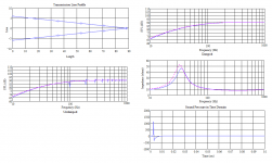
Assuming the object is to attenuate the backwave, progressive rate damping can be very useful for short lines (open & sealed) as it reduces the possibility of mass-loading the driver diaphragm / suspension. Longer sealed lines typically don't need much. For e.g. the attached. This is not optimised, just a highly tapered sealed line, end-loaded to provide maximum excitation of the fundamental & harmonic modes for clarity. On the left: completely undamped. Not exactly a terrifying set of resonant modes. On the right, the four walls lagged with damping material ~equivalent to 1in acoustic fiberglass or similar. No stuffing & no density variation in the lagging.
Apologies that I may not be around much now, I'm having to cancel my ISP account due to my finances, so what time I can grab will have to be elsewhere.
Apologies that I may not be around much now, I'm having to cancel my ISP account due to my finances, so what time I can grab will have to be elsewhere.
Attachments
Last edited:
Progressive damping is required to avoid reflections from the change in acoustic impedance. How to do it well is widely studied because it is needed on absorbing boundaries both experimental, e.g. anechoic chambers, and computational, e.g. CAA and some forms of CFD, which have had whole conferences dedicated to the subject. This doesn't mean a small amount of constant density damping material in an overly long pipe won't perform OK but it isn't the optimum way to do it.Assuming the object is to attenuate the backwave, progressive rate damping can be very useful for short lines (open & sealed) as it reduces the possibility of mass-loading the driver diaphragm / suspension. Longer sealed lines typically don't need much.
Narry a problem.
Re progressive rate damping, as I noted, it can be extremely useful in some cases, but the blunt engineering reality is that it is not necessary in many others in order to obtain the desired results. It's a useful tool to have available, no more. I gave one example of a pipe that is very simply lagged, noting there too that it was not optimised nor supposed to be, despite which as can be seen it provides extremely effective suppression of the pipe resonances. Some may prefer something else; if so welcome to the club, but the point is that word example.
Re progressive rate damping, as I noted, it can be extremely useful in some cases, but the blunt engineering reality is that it is not necessary in many others in order to obtain the desired results. It's a useful tool to have available, no more. I gave one example of a pipe that is very simply lagged, noting there too that it was not optimised nor supposed to be, despite which as can be seen it provides extremely effective suppression of the pipe resonances. Some may prefer something else; if so welcome to the club, but the point is that word example.
Last edited:
With a mid-range driver or higher, you have many kinds of simple and quality ways to address the rear wave. And by "simple", nobody could be thinking of a TL.
We almost exclusively use midTLs to load the midTweeters in our WAWs. They are as simple as other mid enclosures and have significant advantages.
And unlike most that are designed to extend the bass (including Bailey’s example), they are closer to the goal stated in the title of his seminal article: A Non-resonant Loudspeaker Enclosure Design.
dave
I've just read that article Dave, as I still want to try a big version on my midbass drivers at some point. I never knew that chipboard is a better material than plywood!
")
Rob.
I ve got some question about design of a closed tappered transmission line (1/2 line):
Is there an optimum value ( or a ratio/rule of thumb / boundary determining the effectiveness of principle) for surface area of the entry of a closed TL (the largest end of the transmission line) relative to the driver cone area /sd? I understand this is flexible as Dave already pointed in the loudspeaker example in a previous post, and as well that a limit factor may be the volume needed for the driver to behave as expected but i suppose there is a 'sweet spot' in the design parameters/criteria?
Is there some freeware/software which could help design the contour for an exp tapped line?
In the case of a folded line if a lowpass is created using an abrupt bend/knee in the line as in PMC speakers is it possible to predict at which frequency it will occur or this must be empirically determined? Could it be detrimental in a case of a125/ 250hz to 1k/2khz bandpass target?
And Dave, is it possible fot you to list the advantage you find to the principle as you have amount of experience with it?
Last edited:
The large side should match the cross sectional area of whatever generates sound. Ideally the woofer cone generates plane waves which are directly fed into the tapered pipe. Of course there is a magnet at the rear of a woofer, so the path of the pipe bends around it. What's important is that the cross sectional area decreases exponentially, even for the path around the magnet.
Software for designing the contour isn't necessary, cross sectional area just decreases exponentially. Diameter is 2*sqrt(area/pi). Parameters are starting area and how fast it tapers. And somewhere you have to truncate it, otherwise it becomes infinitely long.
Software for designing the contour isn't necessary, cross sectional area just decreases exponentially. Diameter is 2*sqrt(area/pi). Parameters are starting area and how fast it tapers. And somewhere you have to truncate it, otherwise it becomes infinitely long.
I think this is correct for the fundamental tuning of the TL, but the initial cross section and irregularities in the initial taper can cause reflections that generate ripples in the mid-range response. This is actually the most critical part in a mid-range or mid-base TL as the lower end is usually discarded or at least attenuated in the crossover. Of course with a passive X-over killing the impedance peaks is beneficial to the ease of design.
It's correct, period. Sorry. There is truth in the need to avoid excessive driver proximity to boundaries &c. or you can mass-loaded it, or run into unwanted reflections. But that applies to all enclosures, irrespective of type. Otherwise, unless very severe, in which case the basic design is clearly flawed for generic reasons not exclusive to TLs, it's something of a moot point since the higher frequency wavelengths in question are very easily damped out with only modest amounts of material. This is not new, and well understood. There are people here (myself included) who have been designing TLs of all descriptions for many years so we aren't speculating. That's also why there is little particular gain in using exponential tapers for sealed midTLs vis-a-vis a simple conical or linear taper of the same tuning & Vb. It doesn't do any harm, but it doesn't bring any major benefits either, since the main differences tend to be in the location & amplitude of harmonic modes, which are not especially large in a well-designed line & easily damped out anyway.
Sorry. There is truth in the need to avoid excessive driver proximity to boundaries &c. or you can mass-loaded it, or run into unwanted reflections. But that applies to all enclosures, irrespective of type. Otherwise, unless very severe, in which case the basic design is clearly flawed for generic reasons not exclusive to TLs, it's something of a moot point since the higher frequency wavelengths in question are very easily damped out with only modest amounts of material. This is not new, and well understood. There are people here (myself included) who have been designing TLs of all descriptions for many years so we aren't speculating. That's also why there is little particular gain in using exponential tapers for sealed midTLs vis-a-vis a simple conical or linear taper of the same tuning & Vb. It doesn't do any harm, but it doesn't bring any major benefits either, since the main differences tend to be in the location & amplitude of harmonic modes, which are not especially large in a well-designed line & easily damped out anyway.
Last edited:
And Dave, is it possible fot you to list the advantage you find to the principle as you have amount of experience with it?
They have an openness that is often missing in a sealed enclosure, althou to be fair they are usually larger than what most would use sealed.
The impedance peak is highly attenuated. From the first version of Tysen.
A thread for Tysen and variations on FAST
dave
- Home
- Loudspeakers
- Multi-Way
- Was Nautilus bunk?