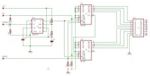
Just another Up-Down-Converter which was designed some 10 years ago and still works fine in one of my pre-amps. Due to the instability with the full 8-bit resolution of the ADC0804, I decided to use “only” the last 6-bit (64 steps), which is normally enough I think. Anyhow, maybe useful for some of us.
Attachments
Hi Jens,
Am wiring up your 8 bit controler right now. Am hand wiring on perf board for testing out....Do you have a pcb for this also, or did you hand wire yours?
Take care,
Mark
Am wiring up your 8 bit controler right now. Am hand wiring on perf board for testing out....Do you have a pcb for this also, or did you hand wire yours?
Take care,
Mark
Even the 8-bit volume control was designed some 10 years ago, but on another EDA tool as the one I use since 5 years or so. During the last few week I got quite a lot of emails asking for the layout, but I couldn’t find the old file. The schematic was already redrawn on my new EDA tool last August and now, I’m happy to say, even the layout which you will find in the appended zip-file - have fun… 😀
Attachments
Thanx Jens
This makes it a lot easier 🙂
ps : what type of volume control do you prefer ?
Greetz,
Nick
This makes it a lot easier 🙂
ps : what type of volume control do you prefer ?
Greetz,
Nick
I built Jens 8 bit control this weekend. If I have the connection to the right of D-11 in circuit that essentially connects pin 1, and pin 10 of the counter I.C.s together.......that doesn't seem correct to me. Seems to work fine if I leave that jumper disconnected. Just wanted to check and see what others might think about that........
Mark
Mark
I’m at work and don’t have excess to my files but just downloaded the schematic from this thread. It seem to me, that the EDA tool created/shows a connection between D11 an pin 1 of U2 themselves, which is nonsense. As you can check, this connection is „only“ shown on the printout of the schematic but not happen on the layout. I believe it’s printing problem (EDA or Acrobat) “only”, simply no connectivity error or missing connection was shown when I checked the final layout. Anyhow, I’ll check an confirm this later today when I’m at home. 

Just checked the schematic of my 8-bit volume control, which was made available as a zipped PDF-file on page 1 of this thread. Don’t ask me why, but my EDA tool added automatically three junctions during the print of the schematic. Two of these junctions are irrelevant, but the one on the cathode of D11+Pin1 of U2 is wrong - sorry that I haven’t seen it before. Anyhow, the layout, even available on this thread, is okay. Append you will find the “cleaned” schematic. 
Attachments
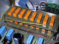
Jens, Thank you for posting the corrected version!! ow mine works perfectly. I will try to post some pictures later. I put the Relays on a seperate PCB so I can try different controllers with them....
Also, what exactly is the function of D-11?
Mark
Also, what exactly is the function of D-11?
Mark
Mark - D11 is part of the circuit around U4, which stops the counter to count when the minimum (00000000) or the maximum (11111111) is attained - Jens
Hi, Just a little project update.
I'm working at the PCB layout, still not finished.🙄
Today I recieved the relays. I couldn't get what I wanted localy, so I bourght Omron G5V-2-12VDC relays from Elfa. They arrived in a 15x10x60cm large box! I ordered enough to make a input selector boad as well.
But, I have to set the project on hold untill Friday. My school project on intelligent building installations are due Friday morning, so this has top priority right now.
Good news though. The other week I made PCB layouts (single sided) of the Aleph L 1.2 PSU and preamp board, I plan to release them the same time as the volume board. So, in a short time I got a complete project for the ones interested.
Hi,
I work on such attenuator too, and I see one problem.
With the Pass Aleph P 8bit it will go down only to -48dB.
If one uses 10 bit it will go down to -60dB
The problem:
For example, if the attenuation is -6dB, the smallest resistor will be switched to ground and all the rest will be switched in parallel to the input.
That means through the largest of the paralleled resistors flows a very little tiny small current, and I am afraid the relais do not like that. 🙁
Am I wrong ? What do You think ?
So for first alternative, I have already built an attenuator that switches shunt resistors to ground -1 -2 -3 -4 -5 -6 -7 -8 -9dB and after a buffer -10 -20 -30 -40 -50 -60dB.
So by using a decade counter it is 0 to -69dB in 1dB steps.
Second alternative is a 8 relais x 8 relais matrix, 8 colums and 8 rows of resistors with a fixed shunt resiszor to ground:
First row 0 -1 -2 -3 -4 -5 -6 -7dB, second row -8 -9 -10 -11 -12 -13 -14 -15dB and so on.
Row relais 3 + column relais 2 means -10dB.
Badly, 64 resistors per channel are needed, all with strange values.
Any ideas, comments ?
I will use an Eprom to pick out the right combinations for the 10bit Pass, and for the display driver.
Greets, Bernhard
Jens said:Just a short inspiration about the attenuation in my “Balanced Zen Line Stage”
Nice boards ! Are they already posted 😉
If not, could you ?
Grtz,
Nick
are you sure...
Are you sure is a good think to split the signal throw so many devices with probably different length path?
Giorgio
Are you sure is a good think to split the signal throw so many devices with probably different length path?
Giorgio
Hi, This is a rough sketch of what I had in mind. Being a novice when it comes to ic stuff, I would be happy to get some input one this one. The idea is that the 555 timer provides a counting pulse whenever a voltage is connected at either up or down. The count input is normally held low with a pull down resistor, and counts up only when a voltage is present.
So will this work?
I still have to figure out a way to display level, since volume will be set by buttons or a rotary giver and not a pot. I would like to use 7-segment displays but then I would have to figure out a simple way to do binary->bcd conversion.
So will this work?
I still have to figure out a way to display level, since volume will be set by buttons or a rotary giver and not a pot. I would like to use 7-segment displays but then I would have to figure out a simple way to do binary->bcd conversion.
Attachments
Bernhard - I use in my Balanced Zen Line Stage (see above) voltage divider of 40db(MSB), 20db, 10db, 5db, 2.5db, 1.25db, 0.62db and 0.31db(LSB), which means we get nearly -80db control out of the 8-bit converter. BTW: 6-bit still delivers -76db with single steps of 1.25dB - Jens 😎
Jens,
Thanks for your schematic and description of the attenuation. Could you post the resistor values and connections to the relays to achieve the 80dB control for the 8-bits. Thanks.
Thanks for your schematic and description of the attenuation. Could you post the resistor values and connections to the relays to achieve the 80dB control for the 8-bits. Thanks.
I am using the same resistor values as in the Aleph version 1.7 preamp. That should work, but perhaps Jens did something else with his.....I know this will work with the A to D controller posted on this thread. I made my relay bopard and circuit comtroller board seperate so either can be used differently, or so the relay board can be used with other controlers....
Mark
Mark
- Status
- Not open for further replies.
- Home
- Amplifiers
- Pass Labs
- Wanted : design PCB for relay controlled volume