SY is right. Sorry!
And yes, your loadline is too "steep" for good linearity
I agree, 90 degree angle from the general direction of curves angle will probably give the most linearity. in this case though, I dont see much distortion anyway. I guess the tube is very linear. I also tried with 12au7 at 300v, 25ma, -4V, its less steep than 6sn7 line, the distortion is still some 8 times higher. any other negatives of a steep loadline?
I am planning to get a transformer custom wound for this. Thinking of the following specs, let me know if it looks good. I can get any of ei, torroidal or r-core, which one will be a good idea for this. I might add a buffer to this at a later date, maybe using ecc88. i could get 300vdc using ez80 and a clcrc filter using 20h choke. idea is to get a generic kind of transformer for preamp uses. is the power enough?
300-0-300v, 100mA
6.3-0-6.3 - 3A
5v - 4A
300-0-300v, 100mA
6.3-0-6.3 - 3A
5v - 4A
I am planning to get a transformer custom wound for this. Thinking of the following specs, let me know if it looks good. I can get any of ei, torroidal or r-core, which one will be a good idea for this. I might add a buffer to this at a later date, maybe using ecc88. i could get 300vdc using ez80 and a clcrc filter using 20h choke. idea is to get a generic kind of transformer for preamp uses. is the power enough?
300-0-300v, 100mA
6.3-0-6.3 - 3A
5v - 4A
Do you really mean 6.3 - 0 - 6.3 (i.e. 12.6 volts end to end)?
Or do you mean 6.3 volts, centre tapped, which would be 3.15 - 0 - 3.15 ?
I would also be inclined to allow the 5v winding to have a 6.3v option - so 0 - 5 - 6.3v which would allow greater flexibility in the choice of rectifiers.
Last edited:
6.3-0-6.3 also gives me the option to run 12v tubes, even the 8v ones with regulation. 5v is for rectifiers.Do you really mean 6.3 - 0 - 6.3 (i.e. 12.6 volts end to end)?
Or do you mean 6.3 volts, centre tapped, which would be 3.15 - 0 - 3.15 ?
I would also be inclined to allow the 5v winding to have a 6.3v option - so 0 - 5 - 6.3v which would allow greater flexibility in the choice of rectifiers.
how 0-5-6.3 gives greater flexibility, i still have both 5 and 6.3 volt windings.
I agree, 90 degree angle from the general direction of curves angle will probably give the most linearity.
This does not make sense. The angle depends on how the vertical axis is scaled! Best linearity always comes with most horizontal load line.
Yes, but the rectifier heater winding is often at HT voltage (depending on the rectifier sometimes connected directly to HT). Even if not connected directly, it is bad practice to use the same 6.3v winding for rectifier and the rest of the circuit. That's why I suggested having a 0 - 5 - 6.3 winding for the rectifier - quite separate from any other heater winding which will often be biased near to zero volts.how 0-5-6.3 gives greater flexibility, i still have both 5 and 6.3 volt windings.
K, lots of people suggesting stuff the OP didn't want. I realize it's all about education, but if the guy wants a unity gain line stage why not just address that? There are lots of good reasons why someone might want this even in today's digital age. If I needed one, I might go for Pete Millet's Low-mu preamp (featured in AudioXpress 2/04). Gain is less than 2 (with the 6AS7). Plenty of designs over the years that completely dispel the suggestion that this application can't be done well with tubes. Check the specs at the bottom of the linked page. Should be good enough for anyone.
This does not make sense. The angle depends on how the vertical axis is scaled! Best linearity always comes with most horizontal load line.
possible, i am a newbie, it kinda geometrically made sense to me, maybe i am wrong.
Yes, but the rectifier heater winding is often at HT voltage (depending on the rectifier sometimes connected directly to HT). Even if not connected directly, it is bad practice to use the same 6.3v winding for rectifier and the rest of the circuit. That's why I suggested having a 0 - 5 - 6.3 winding for the rectifier - quite separate from any other heater winding which will often be biased near to zero volts.
ok, so it will be like this -
300-0-300v, 100mA
6.3-0-6.3 - 3A
0-5v-6.3 - 4A
anything else i can ask the trafo maker to do to make it better.
K, lots of people suggesting stuff the OP didn't want. I realize it's all about education, but if the guy wants a unity gain line stage why not just address that? There are lots of good reasons why someone might want this even in today's digital age. If I needed one, I might go for Pete Millet's Low-mu preamp (featured in AudioXpress 2/04). Gain is less than 2 (with the 6AS7). Plenty of designs over the years that completely dispel the suggestion that this application can't be done well with tubes. Check the specs at the bottom of the linked page. Should be good enough for anyone.
thanx. i have seen that design, looked pretty good. this is going to be a long journey, so it doesnt matter which one is first. i plan to tweak this, add another stage etc. also plan to make a cf later. A phone pre is also on the cards as i recently got hold of a tt.
Make it 2 separate 6.3V windings that way you got more options.
Parallel/series and you can run them at different potentials.
thanx, that is a good idea.
300-0-300v, 100mA
0-6.3 - 4A
0-6.3 - 4A
0-5 - 4A
Its been a long time and i havent done anything yet with tubes, but the good thing is that I have learned a lot of things since I tried it last. I want to make this preamp this time") .
.
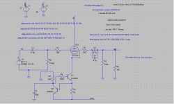
I plan to use an ecc88 (I've got max variants for this and its a nice tube) and since most of my sources have plenty of output voltage, will go for a unity gain buffer with a ring of two ccs. I got the best sim numbers with about 55-60v plate voltage and about 15ma current.
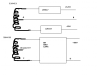
I have a 12-0-12 transformer that I can use to generate about -12v for the ccs using lm337. The other winding I plan to use to generate +6.3v using lm317. Both trafos are EI.
For HT, I have a 22-0-22 transformer that will give me about 61v dc after ditching the center tap. I also have +-35 trafo at hand If I want to go for a higher voltage for B+. Inductors are expensive and a headache to get, so I will go with a crc or crcrc filtering.
One potential issue I see with this is that the Vgk is varying from -140mv to -340mv (with a 2V RMS sinewave signal), is it too close to 0v. If I use a 95v B+, then it varies from about -1.3 to 1.5v. Is this even an issue.
How do I go about grounding the two supplies together, and what about the Protective chassis earth point. I plan to make a pcb for pre and psu, but I would probably breadboard it before trying the pcb.
.I plan to use an ecc88 (I've got max variants for this and its a nice tube) and since most of my sources have plenty of output voltage, will go for a unity gain buffer with a ring of two ccs. I got the best sim numbers with about 55-60v plate voltage and about 15ma current.
I have a 12-0-12 transformer that I can use to generate about -12v for the ccs using lm337. The other winding I plan to use to generate +6.3v using lm317. Both trafos are EI.
For HT, I have a 22-0-22 transformer that will give me about 61v dc after ditching the center tap. I also have +-35 trafo at hand If I want to go for a higher voltage for B+. Inductors are expensive and a headache to get, so I will go with a crc or crcrc filtering.
One potential issue I see with this is that the Vgk is varying from -140mv to -340mv (with a 2V RMS sinewave signal), is it too close to 0v. If I use a 95v B+, then it varies from about -1.3 to 1.5v. Is this even an issue.
How do I go about grounding the two supplies together, and what about the Protective chassis earth point. I plan to make a pcb for pre and psu, but I would probably breadboard it before trying the pcb.
Attachments
It could be an issue. If it gets too close to 0V then you get grid current. Some valves start this from about -1V - but it varies from sample to sample and may change with age. Grid current will introduce distortion and noise unless you can always feed it from a low impedance source - but then you would not need a cathode follower at all!doors666 said:One potential issue I see with this is that the Vgk is varying from -140mv to -340mv (with a 2V RMS sinewave signal), is it too close to 0v. If I use a 95v B+, then it varies from about -1.3 to 1.5v. Is this even an issue.
A good valve model will include realistic grid current. Try simulating with a resistor in series with the signal source. If the distortion varies as you vary the resistor then you have grid current in the model.
(...) the output
any power transformers (220) rated at 10 watts, with
output voltage of about 10 volts.
The power transformer capacity of at least 20 watts (...)
An average quality power transformer used as an output transformer?
IMHO that is NOT a good idea.
It could be acceptable if all you want is playing with tubes.
Not if you are seriously interested in listening good music.
By the way, an average quality power transformer is not suited for audio even when you use it as power transformer.
An audio grade power transformer is a totally different beast:
different core
used in a different point of magnetizing curve
different winding design
different winding tension
different winding structure
different insulation materials
different impregnating material.
Different Sound.
Last edited:
B to D.doors666 said:For grounding, do I short A with C or B with D.
- Status
- This old topic is closed. If you want to reopen this topic, contact a moderator using the "Report Post" button.
- Home
- Amplifiers
- Tubes / Valves
- Want to make a tube preamp