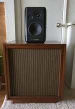
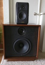
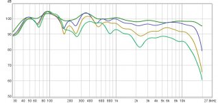
Through a combination of happenstance and experiments I ended up the some “Franken Speakers”. They are made from Sonus Faber Concertos and Bozak 302A cabinets with SB34NRX75-6 drivers (Bozak Mid range not hooked up) tri-amped with op-amp based LR-4 crossovers at 300 Hz and 3000 Hz. The Sonus Fabers are positioned to be time aligned with the Woofers at the 300 Hz crossover point. I had some issues (not surprising) with integrating the Mid and Woofers with a 8 db “shelf / dip” between 120 Hz and 700 Hz (there is no “dip/shelf” with near field measurements of the individual drivers). I tried several different ways to “fix” this and finally ended up using rephase which actually worked well and I am happy with the way these sound now. I would like to learn from this experiment and was wondering if someone could explain why the “shelf/dip” is happening. I understand about “baffle stops” and “sharp edges” and just looking at the radical different designs stacked on top of each other I am not surprised there were issues just curious if this result was “predictable” and if so what the mechanism is so I can use this information on future projects. Thanks.
Attachments
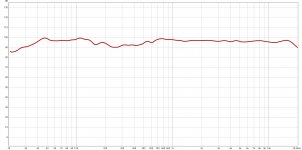
That's pretty impressive fr response. Care to post few off axis plots too?
OK will run and post later
Not really, I am curious as to why the big dip at 300 Hz .... probably has something to do with the sharp edges and big transition of baffle width and driver spacing... I don't know which is why I asked as some one here probably knows...bla bla bla - look what I did
That's pretty impressive fr response. Care to post few off axis plots too?
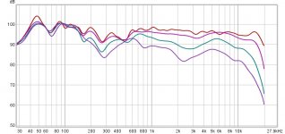
Attached are measurements with and without DSP on axis, 30 degree, 60 degree and 90 degree off access. Taken at 1 meter 1/12 octave gating 1/12 octave smoothing. The "dip" really shows up off access.
Attachments
Hmm, what are the inside dims of the woofer's recessed baffle?
Also, out of curiosity WRT 'Rephase'/FIR filters, which I know nothing about; the 1st approximation for a 300 Hz/4th order offset wired in phase is ~SoS/4/300 = ~11.25-11.3" between driver VCs depending on the SoS used, but doesn't seem to be much offset in the photo, yet correct.
GM
Also, out of curiosity WRT 'Rephase'/FIR filters, which I know nothing about; the 1st approximation for a 300 Hz/4th order offset wired in phase is ~SoS/4/300 = ~11.25-11.3" between driver VCs depending on the SoS used, but doesn't seem to be much offset in the photo, yet correct.
GM
Also, out of curiosity WRT 'Rephase'/FIR filters, which I know nothing about; the 1st approximation for a 300 Hz/4th order offset wired in phase is ~SoS/4/300 = ~11.25-11.3" between driver VCs depending on the SoS used, but doesn't seem to be much offset in the photo, yet correct.
GM
Scratch that, had another 'senior moment'
 , been so long since I did any physical alignment it took me awhile to remember that it would be a 1 Hz offset = ~ 45.2" in phase and 0" offset in reverse phase, which you apparently did, so never mind.
GM
Since the near field measurements of the individual drivers don't exhibit a dip in between 120 Hz and 700 Hz it is likely that floor/ceiling reflections or room modes are responsible for the dip at the measurement mic position.I had some issues (not surprising) with integrating the Mid and Woofers with a 8 db “shelf / dip” between 120 Hz and 700 Hz (there is no “dip/shelf” with near field measurements of the individual drivers).
Hello and thank you. While the very near field measurements (less than 1") are OK the "dip" shows up consistently from 24" to listening position from both speakers (due to location of my speakers they have different room interactions). This is why I don't think it is room interaction. I am thinking it has something to do with the unusual physical orientation of the Woofer and Mid-range. The mid-range, in order to be time aligned with the woofer is 4.5" from the front of the woofer enclosure. Because the "dip" is hard to fix with EQ I am looking for a "physical solution" if one exists.Since the near field measurements of the individual drivers don't exhibit a dip in between 120 Hz and 700 Hz it is likely that floor/ceiling reflections or room modes are responsible for the dip at the measurement mic position.
Hi levimax,
how do you know your active XO circuit is operating exactly as described? Did you measure crossover only to verify that? Where was the mic positioned while you were taking a measurement from the opening post?
Hello Lojzek:
I did check the crossover with an oscilloscope when I built is several years ago and it seemed to be working OK but I did not test it carefully. I will recheck carefully.
The original post was the average of six measurements taken at and around the listening position with both speakers playing and then "Psychoacoustic" smoothing applied. I did this to show the "dip" without a bunch of other "noise". The "dip" shows up consistently from 24" to listening position on both speakers.
Can you please post your nearfield SB34 measurement and also a "raw" farfield SB34 measurement - without any DSP/ crossover etc....
The SB acoustics factory graph shows a rolloff from 100Hz anyway on an IEC baffle. This may be exacerbated by your smaller baffle.
i.e. natural driver rolloff could be contributing to the dip.
The SB acoustics factory graph shows a rolloff from 100Hz anyway on an IEC baffle. This may be exacerbated by your smaller baffle.
i.e. natural driver rolloff could be contributing to the dip.
It supposed to be LR 4 at 300 Hz .... I will check to see what it actually is. Thanksalmost looks like the woofer crossover point may be down around 200hz while the mid cross is up around 300?
Can you please post your nearfield SB34 measurement and also a "raw" farfield SB34 measurement - without any DSP/ crossover etc....
The SB acoustics factory graph shows a rolloff from 100Hz anyway on an IEC baffle. This may be exacerbated by your smaller baffle.
i.e. natural driver rolloff could be contributing to the dip.
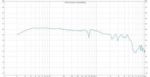
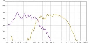
Attached are nearfield Woofer and mid-range with no DSP which I had. I will test far field later when home
Attachments
Thank You
Thank you everyone for your helpful responses. Attached are near field and 1 meter measurements of mid and woofer. It does looks like the crossovers are not working correctly as the Woofer is down ~10 dB at the 300 Hz crossover point instead of 3 dB. The mid-range x-over seems to be working correctly. Take a look at let me know if I am looking at this correctly. I will get to work on the X-over and update when fixed.
Thank you everyone for your helpful responses. Attached are near field and 1 meter measurements of mid and woofer. It does looks like the crossovers are not working correctly as the Woofer is down ~10 dB at the 300 Hz crossover point instead of 3 dB. The mid-range x-over seems to be working correctly. Take a look at let me know if I am looking at this correctly. I will get to work on the X-over and update when fixed.
Attachments
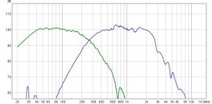
yes it looks like the crossover may need to be aligned better. Mid is close to 300 but even it may need some adjustment for best sound
Woofer is down too far at 300
BTW I don't know how good that woofer is, but U may want to experiment if u can with crossovers between 300-500. Music's "power region" is roughly between 80-400 hz. Sometimes IF the woofer is good above 300hz , crossing at 4-500 can put all that load on woffer and the system can do dynamics a little better.
Most larger woofer I have heard really cannot do above 300 all that well, but when they can I sometimes find a 400 -500 hz cross to be better.
AND lastly I would do that cross by ear. Yes get it spot on in measurement, then play with each cross a bit. Sometimes getting this region fitted to your room can help. You may end up finding the curve you had wasn't that bad depending on room Ha
Last edited:
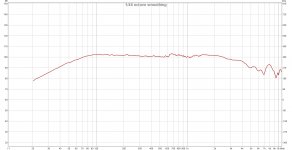
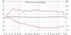
OK I took the active crossover out of the system and temporarily replaced it with the passive parts from the original speakers and one amp (which have same x-over points of 300 Hz and 3000 Hz). I figured it would take me some time to "fix" my active crossover since I have to change resistors and caps to make any changes. When I carefully tested the active x-over on an oscilloscope it was working perfectly with -6 db at 300 Hz for both the high pass and low pass. I guess there is a difference between "electrical performance" and "speaker performance". I measured how my cobbled together passive x-over was working and I was surprised. Smoother response than the active with much less "dip" and pretty good phase ... sounds good too nice and smooth. This has me thinking that for the 300 Hz x-over maybe I don't need or want 24 db per octave? Picture of response of passive at 1 meter attached.
Attachments
- Status
- This old topic is closed. If you want to reopen this topic, contact a moderator using the "Report Post" button.
- Home
- Loudspeakers
- Multi-Way
- Want to Learn from my Franken Speakers