Sheldon said:
Did you read the link?
Sheldon
Ok, I understand your point now.
Cheers,
45
45 said:Ok, I understand your point now.
Cool. Problem is, I don't know this stuff well enough to really explain it well. If I had basic competence in LT Spice, I'd sim it. Gotta learn that.
Sheldon
edit: BTW, not arguing that there might not be a benefit to a little larger cap there. Depends on the final load, of course.
Sheldon said:
Cool. Problem is, I don't know this stuff well enough to really explain it well. If I had basic competence in LT Spice, I'd sim it. Gotta learn that.
Sheldon
You have simply to derive again the expressions of new impedances using the complex vectors and will get a new formula.
Attachments
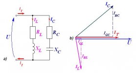
The new formula is something like this (look at the bottom where it says phase definition):
http://hyperphysics.phy-astr.gsu.edu/hbase/electric/parres.html#c1
Cheers,
45
http://hyperphysics.phy-astr.gsu.edu/hbase/electric/parres.html#c1
Cheers,
45
Thanks 45, but I couldn't make sense of the numbers by just plugging in values for our circuit. I did get LT Spice to work (I think). At least the graphs made sense as I played with values. In this circuit, by the time the load resistor reaches 100k, the phase at 20 Hz, varies only by about 8 degrees from a circuit without the inductor (19 vs. 27) The difference at 20Hz is zero as the load resistor is increased to 200k (19 vs. 18.5). Logically the the slope is a little steeper with the LC circuit, but it's monotonic. I think one can safely say, that at these values, the RC constant of the C and load dominate the outcome. As for audibility; well, speaker effects will be far greater at these frequencies.
Sheldon
Sheldon
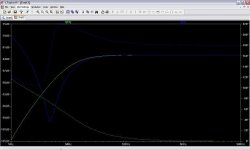
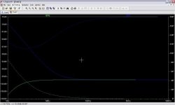
Did a little more play with the Spice model. The frequency of the resonance point does move around with changes with the resistance in series with the cap. But it doesn't change that much. That aspect appears largely unimportant for this purpose. Of course, changing the cap value does change the frequency in proportion to the cap value. So, as 45 noted, the major effect of the resistance is to dampen the resonance. However, the damping is essentially complete at these values, so that there is no dip in level or warble in the phase response.
BTW, it only takes three components to model pretty well; voltage source, inductor, and cap. The respective resistances can all be entered as part of the component characteristics, e.g., ESR for the cap, DCR for the inductor, and Z for the source.
Sheldon
BTW, it only takes three components to model pretty well; voltage source, inductor, and cap. The respective resistances can all be entered as part of the component characteristics, e.g., ESR for the cap, DCR for the inductor, and Z for the source.
Sheldon
Sheldon said:Did a little more play with the Spice model. The frequency of the resonance point does move around with changes with the resistance in series with the cap. But it doesn't change that much. That aspect appears largely unimportant for this purpose. Of course, changing the cap value does change the frequency in proportion to the cap value. So, as 45 noted, the major effect of the resistance is to dampen the resonance. However, the damping is essentially complete at these values, so that there is no dip in level or warble in the phase response.
BTW, it only takes three components to model pretty well; voltage source, inductor, and cap. The respective resistances can all be entered as part of the component characteristics, e.g., ESR for the cap, DCR for the inductor, and Z for the source.
Sheldon
Do you have a plot of the phase as function of frequency for different values of the resistor?
Cheers,
45
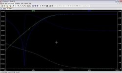
Yes, as noted earlier, with the inductor in the circuit and 100k load, the phase rotation is about 28 degrees, and about 19 degrees without. With the inductor, the cap or load resistor can be increased to bring the phase rotation to the same as without the inductor.
Sheldon
Sheldon
How much do you need to increase that resistor when using the choke?
Anyway you could be a bit limited by the requirement of high input impendance from the power amp.
I think that for few volts output swing a 2.2-3.3uF high quality cap would sound "transparent".
I did it in a power amp and worked very well using the SCR's MPK.
Cheers,
45
Anyway you could be a bit limited by the requirement of high input impendance from the power amp.
I think that for few volts output swing a 2.2-3.3uF high quality cap would sound "transparent".
I did it in a power amp and worked very well using the SCR's MPK.
Cheers,
45
Either doubling the cap or doubling the resistor brings the phase rotation at 20Hz to about 18 degrees. I recommend downloading SwCADIII. It's free on Linear's web site. http://www.linear.com/designtools/software/ltspice.jsp And, a circuit like this is perfect to learn the basic functions. It's reasonably intuitive, as these things go. I'm a raw neophyte, but can show you how to do this simple circuit. I've found PSUD very useful, and I intend to play more with this one.
Sheldon
Sheldon
An externally hosted image should be here but it was not working when we last tested it.
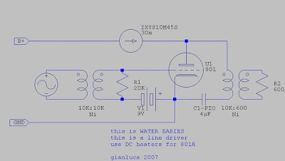
I found another circuit on seam tube ( same in triode direct hitting not complete points). 801 is quit rare tube and I have just two of them in my junk box .
[IMGHTTPSDEAD]https://www.tubeworld.com/801a_rca.jpg[/IMGHTTPSDEAD]
Hey! That's me! Lovely preamp 
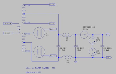
I modded it a number of times: CCS is now a couple of cascoded mosfet (much better now). PSU is a standard LCLC. Filaments are heated by a small-C LC filter and a LM1084 CCS. OH! And I am using 211.
Click here to see the pic
I modded it a number of times: CCS is now a couple of cascoded mosfet (much better now). PSU is a standard LCLC. Filaments are heated by a small-C LC filter and a LM1084 CCS. OH! And I am using 211.
Click here to see the pic
- Status
- This old topic is closed. If you want to reopen this topic, contact a moderator using the "Report Post" button.
- Home
- Amplifiers
- Tubes / Valves
- vt25 in pre amp