.. to be honest, it worked so well as originally specified by Lazy Cat, and later modified by Shaan for the Renesas latfets, I did not experiment with the output bias much at that time. We can certainly try it...
wouldn't the best bias figure/point be where it is stable, and DC on output also is balanced and stable ?
I do know how it sounds when 'crancking' up the bias on AB amps
tried it many times, and never liked it much really
some perceive it like the sound is becoming warmer and fuller
I hear it as getting more muffled
personally I think its more a speaker problem
stricktly IMO, ofcourse

Yes. It is stable, and to the best of my ability to verify with small-signal and sub-clipping signals, it works very well at the ~160ma specified by Lazy Cat, and a good margin above that. To get to this point with my latest layout, and with Renesas latfets on my test boards, I set the VAS bias a bit higher than the 12 mA recommended by LC, and later by Shaan. 13~15 mA, depending on other test conditions, aiming for the 160 mA mark.wouldn't the best bias figure/point be where it is stable, and DC on output also is balanced and stable ?
I have not tried to find the level at which the circuit becomes unstable, or the signal appears obviously degraded.
Yes, and very good insight. This is part of the reason why two people may wish to set the bias to a different level, depending on their speakers, and other circumstances. Higher is not necessarily better. We sometimes assume that based on amplifiers which do sound better while operating in class A mode, but speaking only for myself, I have not noticed this issue with any one of four version of Lazy Cat's VSSA.I do know how it sounds when 'cranking' up the bias on AB amps .... personally I think its more a speaker problem
stricktly IMO, ofcourse
However, since this is only audio, and not brain surgery, I see no reason not to experiment a little...
(for anyone else reading this, please note that I consider an occasional burned VAS transistor or latfet a fair price to pay for some fun with home audio, so experiment at your own discretion...
)Project Status
As of yesterday, all of the basic testing I was planning on has been done. As time allows over the next few days, I will post as many test results as I have time for.
I have enough boards on hand to start sending them out to the people who have been patiently waiting for me to finish.
As of today, I have also ordered a couple dozen more to cover the next group. The boards are small enough that I can get them at a discount even in smaller quantity, so waiting for a bigger order is not really necessary.
This means those who expressed their interest earlier can get boards without much more waiting, and at the same time, it means I have to deal with fewer packages at one time - it will also help compensate for my usual rate of progress
More details in a day or so.
If there are more requests after this, I will open a Group Buy thread.
In either case, I plan to get enough for everyone who has requested boards so far, plus a few spares.
I am also definitely not closing the discussion on components and other suggestions, or alternative builds and layouts from other people, through-hole or otherwise...


I wonder if R18 should be used for both input Gnd and also feedback return Gnd...
In all my VSSA topology versions I have used the 2sa970/2sc2240 high grade version instead of the BC5xxC ones. I wonder if some peoples have compared the two - sound wise - even if we have to twist the pins of the transistors ( different pin out).
The regulated supply for t he front end is useful when you use only resistors instead of the CCS. I have no boards (so far...) that allow me to have CCS instead of resistors so I could not compare the 2 options or used both CCS and regulated supply.
For the pcb layout, is the return paths for input/feedback different from the power supply cap return, so only meeting at star gnd point? Refer to Idefixe pcb layout.
Fab
Last edited:
I'm planning on installing some KSA992F / KSC1845F (my batch of these have hFE in the 400-500 range) for the front end, though I do have plenty of the BC550C / BC560C devices as well.
What I really want to compare is VAS devices. I'm using devices others have quite explicitly told me are 'unsuitable' and 'asking for trouble'. I find in practice they work just fine. I would like to find out what, if any, difference in measured performance and sound there is between the KSA1381E / KSC3503E and these other devices.
What I really want to compare is VAS devices. I'm using devices others have quite explicitly told me are 'unsuitable' and 'asking for trouble'. I find in practice they work just fine. I would like to find out what, if any, difference in measured performance and sound there is between the KSA1381E / KSC3503E and these other devices.
I'm planning on installing some KSA992F / KSC1845F (my batch of these have hFE in the 400-500 range) for the front end, though I do have plenty of the BC550C / BC560C devices as well.
What I really want to compare is VAS devices. I'm using devices others have quite explicitly told me are 'unsuitable' and 'asking for trouble'. I find in practice they work just fine. I would like to find out what, if any, difference in measured performance and sound there is between the KSA1381E / KSC3503E and these other devices.
For the VAS, most peoples are looking for optimized bandwidth and low distortion with lowest cob. It is not wrong but this criteria may disregard interesting other options....sound wise of course. I am not surprised that you find other devices working fine as well... This is an audio amplifier and not an ultrasound amplifier...
Fab
Last edited:
For the VAS, most peoples are looking for optimized bandwidth and low distortion with lowest cob. It is not wrong but this criteria may disregard interesting other options....sound wise of course.
Fab
Those are some of my thoughts too, Fab. If the transistor sounds good and there are no issues with stability or overdrive behaviour then I say use them.
I have been poking around looking for candidates that are current production, readily available and reasonably priced. I have settled on KSA1220AY / KSC2690AY, and plan on testing these in different designs. I can confirm they work fine in my version of the PeeCeeBee and will likely work fine elsewhere.
Not sure about that. i thought that the feedback should be referenced to the same ground as the output.I wonder if R18 should be used for both input Gnd and also feedback return Gnd...
(Of course I reserve the right to change my mind with little or no notice...
)Twisting the pins is probably an OK option, but comparing the two on sound is likely to be difficult. Whatever the effect may be, it will likely be swamped by other influences. Perhaps some kind of test circuit can be devised to show the difference (?)In all my VSSA topology versions I have used the 2sa970/2sc2240 high grade version instead of the BC5xxC ones. I wonder if some peoples have compared the two - sound wise - even if we have to twist the pins of the transistors ( different pin out).
Btw, my second round of checking the hfe of the batch of BC546C/556C I have from one of the other members went well. At the 2 mA input bias we are using, they test quite close. The hfe averages when tested at 2 mA were about 10%-15% apart, not nearly as much as last time.
No. They come together at the main decoupling caps, and from there, about one inch to the ground tab. Basically, the lower edge of the board is a ground. To improve on that to a significant extent, I will have to use the top side of the board. I look at his layouts "for inspiration" all the time...For the pcb layout, is the return paths for input/feedback different from the power supply cap return, so only meeting at star gnd point? Refer to Idefixe pcb layout.
(and I encouraged him to post in this thread, SMDs or not)I should also say that I would not bring the speaker returns to the board to the same crimp connector, like some people are doing with VSSA modules. I can't say about dual supplies, but with a single supply, Cap Multiplier, or my bench supply, it seemed to raise the noise floor of the signal. It does not necessarily create hum or the dreaded ground loop. However the noise floor in my tests, as observed on the scope, goes up quite a bit.
In any case, if 2~3 people are interested in making tweaks, a small layout rev that would incorporate changes like this for proper testing is quite practical. $100 split among 3-4 people is trivial compared to the cost of the parts we are all buying to test with. I am already on the third numbered rev anyway, and there have been two others I did not post. I would not offer it to twenty unsuspecting people, but if you and/or Jason know up front that you are getting an un-tested variant...
why not?YESSSS!...What I really want to compare is VAS devices...
The first version I built to Shaan's original direction, without CCS and without most of the film caps (only two at the main decoupling caps), with Fairchild BD139-16/140-16 sounded really nice. Not as detailed/transparent/whatever-the-word-is as the later versions or the modules from LC, but still, really nice, clean, and a bit warmer sound. (It does need a really clean supply.)I would like to find out what, if any, difference in measured performance and sound there is between the KSA1381E / KSC3503E and these other devices.
The old stock KSC3503E that I have matches up well with one of the new KSA1381E date codes I have from Mouser. Those are what I propose to send out with the boards to people who want them. I have tested three boards with these, and at least according to the specs and the tests, they seem to give the best results so far.
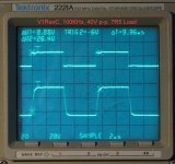
Test Results, Square Wave Sweeps
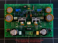
Test results from last weekend, using a board built to incorporate some of the earlier component suggestions. In other words, in the interest of disclosure, this is a tweaked board, incorporating suggestions and comments I have received, compared to the previous tests which were done with the base-line components listed in the BOM. It was built specifically so I could test the limits of the circuit.
Input filter is unchanged for these. Input transistors were hand selected and matched from the old-stock lot of BC546C/BC556C. Feedback 2.2K resistors are Vishay/Dale CPF1 (1== 1 Watt rating). KSA1381E/KSC3503E, matched to 5%, 22pF compensation caps. Zobel not installed. 10uF film caps, C17, C18 not installed.
Poweer Supply: +/-35.5V
Input bias: ~2 mA
VAS bias: ~17 mA
Total Idle current: 154 mA
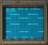
The board is a little "faster" than with the first set of components, and square waves look a bit more symmetric, but the differences are almost not noticeable compared to the last tests. I ran the full sweep, 10 Hz to 100KHz, but there is not much to see below 10K. I am using 10K as the baseline, and to adjust the signal generator, scope, etc.
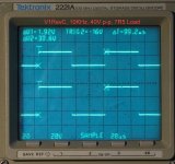
You have to look at frequencies above 20KHz to even detect a difference, or see something interesting, which is why I posted the 100K Hz square wave instead 50K, or 20K.
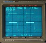
The overshoot at the negative edge of the trace in the unloaded 100 KHz pic is due to a tiny bit of ringing on the negative going output of the signal generator, not visible in the pics. (this may well be another argument for limiting the BW)
The 1W feedback resistor is not something I am proposing for a practical amp at this supply voltage, I simply need it to run continuous-signal tests at higher power, not to listen to music.
Bottom line, 10KHz results for this circuit look like 1KHz from other amps, and it takes a 100KHz square wave before it starts to show its limits...
Test results from last weekend, using a board built to incorporate some of the earlier component suggestions. In other words, in the interest of disclosure, this is a tweaked board, incorporating suggestions and comments I have received, compared to the previous tests which were done with the base-line components listed in the BOM. It was built specifically so I could test the limits of the circuit.
Input filter is unchanged for these. Input transistors were hand selected and matched from the old-stock lot of BC546C/BC556C. Feedback 2.2K resistors are Vishay/Dale CPF1 (1== 1 Watt rating). KSA1381E/KSC3503E, matched to 5%, 22pF compensation caps. Zobel not installed. 10uF film caps, C17, C18 not installed.
Poweer Supply: +/-35.5V
Input bias: ~2 mA
VAS bias: ~17 mA
Total Idle current: 154 mA
The board is a little "faster" than with the first set of components, and square waves look a bit more symmetric, but the differences are almost not noticeable compared to the last tests. I ran the full sweep, 10 Hz to 100KHz, but there is not much to see below 10K. I am using 10K as the baseline, and to adjust the signal generator, scope, etc.
You have to look at frequencies above 20KHz to even detect a difference, or see something interesting, which is why I posted the 100K Hz square wave instead 50K, or 20K.
The overshoot at the negative edge of the trace in the unloaded 100 KHz pic is due to a tiny bit of ringing on the negative going output of the signal generator, not visible in the pics. (this may well be another argument for limiting the BW)
The 1W feedback resistor is not something I am proposing for a practical amp at this supply voltage, I simply need it to run continuous-signal tests at higher power, not to listen to music.
Bottom line, 10KHz results for this circuit look like 1KHz from other amps, and it takes a 100KHz square wave before it starts to show its limits...
Attachments
Bottom line, 10KHz results for this circuit look like 1KHz from other amps, and it takes a 100KHz square wave before it starts to show its limits...
Bravo, nice plots which clearly represent what's VSSA all about, most transparent and resolutive sound reproduction, effortlessly.

In any case, if 2~3 people are interested in making tweaks, a small layout rev that would incorporate changes like this for proper testing is quite practical. $100 split among 3-4 people is trivial compared to the cost of the parts we are all buying to test with. I am already on the third numbered rev anyway, and there have been two others I did not post. I would not offer it to twenty unsuspecting people, but if you and/or Jason know up front that you are getting an un-tested variant...
I'd be game for a set of 'tweaker' boards, in addition to the previously requested current revision. I don't need fully developed and fool-proof, let's play! Let me know about your ideas on this.
YESSSS!
...
The old stock KSC3503E that I have matches up well with one of the new KSA1381E date codes I have from Mouser. Those are what I propose to send out with the boards to people who want them. I have tested three boards with these, and at least according to the specs and the tests, they seem to give the best results so far.
Have you looked to any alternative candidates for the VAS? If so, which have you entertained? I'm most interested in devices in current full production status. I dislike the idea of having to hunt down NOS; those that have them in any real quantity usually know to charge a serious premium.
I started to, in the other thread, but besides you, I could not get much discussion going.Have you looked to any alternative candidates for the VAS? If so, which have you entertained? I'm most interested in devices in current full production status. I dislike the idea of having to hunt down NOS; those that have them in any real quantity usually know to charge a serious premium.
I have close to 300 of the KSC3503E, and over 100 KSA1381 w three different date codes. One of those date codes matches up well with the old-stock KSC3503E, so now that I know, I can order more. I will post the details as soon as I review my notes, but within about 25 pairs, 80% found a 10% or better match.
(Much better than my last attempt)
I got them specifically with nx-Amp and VSSA in mind. Enough for anyone so far, who wants to use them, with no hunting.
Obviously, no matter the number, if we want this design to stay alive, we should have an alternative, but for now, it is not urgent.
Simple: We continue the discussion, collect suggestions, pick a few that make sense, and order a pair each for those who want to experiment. Since I do not need a fully tested board, the effort on my part is minimal... for you, not so minimal, but about the same as testing a board you etched....I'd be game for a set of 'tweaker' boards, in addition to the previously requested current revision. I don't need fully developed and fool-proof, let's play! Let me know about your ideas on this.
Not sure about that. i thought that the feedback should be referenced to the same ground as the output.
(Of course I reserve the right to change my mind with little or no notice...
Twisting the pins is probably an OK option, but comparing the two on sound is likely to be difficult. Whatever the effect may be, it will likely be swamped by other influences. Perhaps some kind of test circuit can be devised to show the difference (?)
Btw, my second round of checking the hfe of the batch of BC546C/556C I have from one of the other members went well. At the 2 mA input bias we are using, they test quite close. The hfe averages when tested at 2 mA were about 10%-15% apart, not nearly as much as last time.
No. They come together at the main decoupling caps, and from there, about one inch to the ground tab. Basically, the lower edge of the board is a ground. To improve on that to a significant extent, I will have to use the top side of the board. I look at his layouts "for inspiration" all the time...
I should also say that I would not bring the speaker returns to the board to the same crimp connector, like some people are doing with VSSA modules. I can't say about dual supplies, but with a single supply, Cap Multiplier, or my bench supply, it seemed to raise the noise floor of the signal. It does not necessarily create hum or the dreaded ground loop. However the noise floor in my tests, as observed on the scope, goes up quite a bit.
In any case, if 2~3 people are interested in making tweaks, a small layout rev that would incorporate changes like this for proper testing is quite practical. $100 split among 3-4 people is trivial compared to the cost of the parts we are all buying to test with. I am already on the third numbered rev anyway, and there have been two others I did not post. I would not offer it to twenty unsuspecting people, but if you and/or Jason know up front that you are getting an un-tested variant...
Hi PMI
For the feedback return just look at Bonsai NX amp and others as well. It is the input and feedback grounds that must be tighten together since they must be free of any noise from high current return such as speaker return or power supply return so no noise is amplified.
I intended to do my own layout to get everything I need but your offer is quite interesting. I know from the NX amp pcb that you deal with a good quality pcb manufacturer. So if the design evolves to my requirements then I would be glad to test the un-tested variant...
I share your thoughts for the speaker return to the power supply for single supply.
Here some of my preferences (wish) for modifications of your last layout:
1) support TO-220 bce pin out for VAS with mounting on top or below pcb - if possible;
2) feedback and input gnd together;
3) separate tracks for gnd return of input/feedback and decoupling caps. Star gnd;
4) at least 2 pairs of MOSFET output and be able to use double die device. I want more than 100 W and be able to drive low impedance speakers;
5) I prefer securing the output MOSFET with big metal washer than with the pcb;
6) possibility to connect a regulated supply for the front end including a tab for the regulator gnd to connect to the star gnd;
7) use bipolar caps for feedback. Good quality value only up to 1000uf so 2 in //;
8) 2 pairs of filter caps for the mosfets;
9) 2W feedback resistors size;
10) footprint to have compensation cap like the NX amp instead of 2 miller caps ( to experiment)
11) small value decoupling cap very close to output mosfets
I realize that the pcb size would need to increase significantly so it may not suit your objective....
Also it may be more work than you hâve anticipated....
Fab
Last edited:
I agree, transparent is a good word to use here.Bravo, nice plots which clearly represent what's VSSA all about, most transparent and resolutive sound reproduction, effortlessly.
I modified one of my other two boards, so I could listen to a stereo set with the last component substitutions (I have a dozen decent pair matches for the VAS transistors now, so I wanted to make a stereo set with those, and the 22pf caps).
In reference to Fab's earlier post, with other circuits, pushing for a "faster" amp has not always produced the best sound, but in this case there is no sign of any brittleness or excessive sharpness in the sound, it stays smooth when it should be, and sharp when called on.
I have been listening most of the evening, and the sound is exceptional, even with a less than ideal listening space. Stan Getz' Lost Sessions really shine, and listening to a few tracks from CD remasters of some early Billy Joel albums, it is easy to tell why he was tagged as a "baritenor", and not a baritone.
(this is as close as I can bring myself to using real audiophool jargon...
 )
)Now onward to a few tracks from Phantom, the original cast recording...
The current layout was made so that the first main decoupling cap combo was balanced relative to the power and ground trace length, and the ground to the front end splits off from that point. The Diode and 10R were located at that point so the 10R effectively separates the rail near the main decoupling cap. The power supply return on the board carries very little current, compared to the +/-supply. This is not an argument against, but just an explanation of what was done, and why. I can certainly re-arrange ground traces as you suggest, but you may lose more than you gain....
Here some of my preferences (wish) for modifications of your last layout:
1) support TO-220 bce pin out for VAS with mounting on top or below pcb - if possible;
2) feedback and input gnd together;
3) separate tracks for gnd return of input/feedback and decoupling caps. Star gnd;
4) at least 2 pairs of MOSFET output and be able to use double die device. I want more than 100 W and be able to drive low impedance speakers;
5) I prefer securing the output MOSFET with big metal washer than with the pcb;
6) possibility to connect a regulated supply for the front end including a tab for the regulator gnd to connect to the star gnd;
7) use bipolar caps for feedback. Good quality value only up to 1000uf so 2 in //;
8) 2 pairs of filter caps for the mosfets;
9) 2W feedback resistors size;
10) footprint to have compensation cap like the NX amp instead of 2 miller caps ( to experiment)
11) small value decoupling cap very close to output mosfets
...
1) I thought I allowed enough room this time (?) Still not enough to mount on a 180 degree turn? If this does not work, I know someone else will be disappointed...
2) OK
3) OK, but see above paragraph.
4) Double-die TO-264 already discussed, and supported, but w. off-board mounting screw, a bit elaborate but workable for a test board. About two pair, see below.
5) See 4.
6) a) already consdered, and space allowed for b) clarification needed.
7) Depends how big (?)
8) What value and diameter, i.e., how much bigger can you stand to make the board?
9) I intentionally left room for longer/wider feedback resistors. Note empty space between R15/R16 and C13.
10) OK
11) Already considered that. This is one of those places where an SMD part can be helpful, b/c you can locate one right at the leads.
The main departure is the double Mosfet pair, and double caps. That makes it a different design and different layout. The double-die TO-264 packages are attractive, because the two devices inside are matched from the factory, but availability is uncertain. Still probably worth looking into. I believe Marc has already posted one like that I really like, have you seen it?
- Status
- This old topic is closed. If you want to reopen this topic, contact a moderator using the "Report Post" button.
- Home
- Amplifiers
- Solid State
- VSSA Through-Hole-PCB build thread