Those are Sprint files, PMI used Eagle as far as I know and he never released his files to the forum. That artwork is a re-draw. I did my own version of the VSSA and have another revision in the works, maybe that will interest some.
I don't know what ever happened to him. I tried to contact him off-board but never heard back. To say he's died is speculation but we can be certain he hasn't posted here in quite some time.
I don't know what ever happened to him. I tried to contact him off-board but never heard back. To say he's died is speculation but we can be certain he hasn't posted here in quite some time.
Here you cand find a clone.
But I don't know if is right to use it without PMI's permission.
PMI will be happy to share his copyright.
Dear Jason, I am interested in get, I did buy one of the complete boards.Those are Sprint files, PMI used Eagle as far as I know and he never released his files to the forum. That artwork is a re-draw. I did my own version of the VSSA and have another revision in the works, maybe that will interest some.
I don't know what ever happened to him. I tried to contact him off-board but never heard back. To say he's died is speculation but we can be certain he hasn't posted here in quite some time.
Best Regards
I have built Jason's version and PMI's Both work perfectly. Sounds like Jason is working on an update so maybe hold tight and see what he comes up with.
Last I heard from Peter (PMI) was December 2013. I really miss him around here. He was always very kind and helpful.
Blessings, Terry
Last I heard from Peter (PMI) was December 2013. I really miss him around here. He was always very kind and helpful.
Blessings, Terry
Thanks Terry for your help here. I didn't know him but seems a helpful man.
I remember you was seeing on the obituaries from his city but is to strange that a man with those fervent activity disappear from day to night. Or is deeply ill or the worst, he died.
Best Regards
I remember you was seeing on the obituaries from his city but is to strange that a man with those fervent activity disappear from day to night. Or is deeply ill or the worst, he died.
Best Regards
Being totally realistic, as PMI received money for his product and has not provided - for whatever reason - there can be no bar upon others who have already paid using the same material. It IS sometimes a sad world and other circumstances DO occassionally overtake the best of us - but life goes on.
That artwork is a re-draw. I did my own version of the VSSA and have another revision in the works, maybe that will interest some.
May we see a piece of what you did/will do ?
Hi Anthony
You seem to try to use my USSA/FSSA manual techniques which consists in testing stages in steps before final assembly. If that is the case, can you be more precise on which components are installed or not. Also, the stages tests technique from my manual need to be adapted for different amplifiers. If you do not have the output transistors installed then your front end circuit may be floating...
Fab
You are being cautious
Have you tried to connect temporarily a jumper between output and middle of D1 and D2 so to have a closed loop.
Also, your J112 may have very different IDSS values where one is much lower than the other. You can replace the one with another J112
It is an easy circuit to troubleshoot so no worry this should be quite easy.
Fab
Last edited:
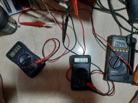
I have no idea what voltage you are showing. 3.5mv is not 35mv...
With power off measure R3 and R4 as really being 470 ohms as per schematics.
Put a jumper between OUT and junction of D1 and D2.
Set power ON and measure voltage cross R5 and then R6. Divide value by 3300 ohms (as per schematics). This will give you the set ID for each J112. They should be similar value and about in the 1.5ma range. Thus voltage across R5 and R6 to be about 4,95 VDC.
Fab
Last edited:
- Status
- This old topic is closed. If you want to reopen this topic, contact a moderator using the "Report Post" button.
- Home
- Amplifiers
- Solid State
- VSSA Through-Hole-PCB build thread
