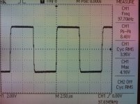
That is outstanding! How are you loading the output?SMD production VSSA PCB started to work immediately from the first power up. It took me 40 seconds to set it to 15 mA VAS bias, zero DC offset and 160 mA output bias. On pic is 2,7 MHz (-3dB) response, perfectly stable.
That is outstanding! How are you loading the output?
At 2,7 MHz is loaded with 10 Ohms from output zobel only. Today's measurements are mostly concentrated to bias and offset leveling, clipping behaviour, stability in general. Output bias is trimmable from 120-200 mA, VAS bias up to 20 mA, offset in both directions ended at 0 mV, so quite happy with the results. Power is not an issue, it is always available if needed.

Well of COURSE, we always need something better...100 kHz on 8 Ohm is the same as an input signal, which comes from an old Elektor signal generator, not really the perfect one. Have to get something better soon.
I am using an old Wavetek for my tests. I am fond of some of those old instruments, they do not seem to fail as often as some of the newer ones I have seen (and heard about)... 
The second channel exactly the same as first. This one set-up even faster, in just 30 seconds.
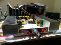
Now all together 6 VSSA channels up and running, my demo VSSA (3rd and 4th channels assembled) is hard working every day from morning till late night hours, been in many audio set-ups demoed, now sourced from NAD M51 and it is pleasure to listen to the combo.
From what I saw up to now I think there shouldn't be any problem with the rest of 250 VSSAs from GB.
Regards, Lazy C.
Attachments
Lazy Cat,
Getting Excited!!
Would 300 watt SMPS be enough for low efficient Speakers (86 db ). Or should i get the 500W. These appear to be the 2 options that i can afford.
Always the one providing more output current, especially if it is a regulated SMPS, which is recommended. 5 A effective is least what must be available if our goal is 100 W/8 Ohm rms and 150 W/4 Ohm rms. To be able to drive your speakers to decent SPL, SMPS should provide +/- 45V exactly.
... what must be available if our goal is 100 W/8 Ohm rms and 150 W/4 Ohm rms....
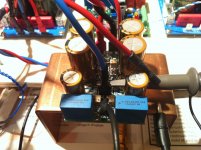
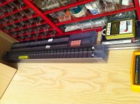
Would you need a larger heatsink than the one you show in pics in some posts above in this thread?Of course, this copper one is intended just for set-up checking. It nicely goes from room temp to 50 deg C in 5 min and stays there, so you don't have to wait too long to se how parameters settled at proper output bias and with temp raise only VAS bias changes from 12 to 15 mA. DC offset and output bias are fixed all the time from heating up. So this copper heatsink is just for testing purposes or to listening the music in a few Watts range.
Understood that, use of quick responding heat sink in test, but thanks.
Even the two aluminum heat sinks I saw in one of your prototypes seem (to me) smaller than what you would need for a +-45V rail, unless I am missing something.
Or to put it another way, if those were the correct size, then we can safely use a much smaller heatsink with 35-40V rails, which is what I think was given as maximum supply somewhere here.
I believe you recommended around 0.5K/watt?
(Forgive me if I missed some part of the thread)
Of course, this copper one is intended just for set-up checking. It nicely goes from room temp to 50 deg C in 5 min and stays there, so you don't have to wait too long to se how parameters settled at proper output bias and with temp raise only VAS bias changes from 12 to 15 mA. DC offset and output bias are fixed all the time from heating up. So this copper heatsink is just for testing purposes or to listening the music in a few Watts range.
I want to build two amps with four pcbs each.
Each amp would be powered from two smpss, one supply for two pcbs. Most of the time all four channels would be switched on to amplify a four way speaker. In order to be more flexible I would like to be able to switch on the supplies independently and (in rare cases) run only one supply powering just two pcbs. In this case the heatsinks most likely will have a different operating temperature.
I assume that DC offset and output bias would not change, but VAS bias would be different compared, correct ?
Do I need to correct for this this or can I just ignore it ? Very ambitious plan you have there, I wish to hear those 4-way speakers some day.
VAS current fluctuations you can simply ignore, VAS current change from 12 mA at cold start to 15 mA at 50°C is of none importance since output bias is fixed with shunt regulator. All amp's VAS bias currents are changing with the temperature, it's just that people not specify or present the issue.
Output DC offset and bias are the same from cold start to all temperature operating conditions. There are not so many amplifiers like VSSA that needs no DC servo and still maintaining 0 mV DC at the output.
thanks LC, good news !
One more thing: the power supply for the woofer and low mid channel obviously needs as much voltage and current as I can possibly get: specs of the Connexelectronic SMPS800R(E) look promising. For mids and highs I thought of using a less powerfull rated smps with lower voltage e.g. SMPS300RE (+/-24V). Doing so I could experiment with different bias settings without creating too much heat. Or do you advise the +/-45 V version here as well ?
Thanks for your help !
thanks LC, good news !
One more thing: the power supply for the woofer and low mid channel obviously needs as much voltage and current as I can possibly get: specs of the Connexelectronic SMPS800R(E) look promising. For mids and highs I thought of using a less powerfull rated smps with lower voltage e.g. SMPS300RE (+/-24V). Doing so I could experiment with different bias settings without creating too much heat. Or do you advise the +/-45 V version here as well ?
Thanks for your help !
For mids and highs I recommend +/-30 Vmin, but rather go to +/-45 V as well. With output bias trimmer installed you can adjust up to 200 mA, for higher bias you would need to change trimmer's serial resistor, but it is possible without any problem. Only that I don't see any advantage since 160 mA is best optimum for ALF.
- Home
- Vendor's Bazaar
- VSSA Lateral MosFet Amplifier