Q: did you test with a series input cap, or just direct coupled? And, do you still have one working channel that you could try with cap at input, and perhaps w. a 1~10R between the input ground lead and the common ground in the box? I don't mean to say to use permanently, but to do a test, one channel only, other channel disconnected from the source at the RCA conn... Isolate the circuit board, & isolate the two channels from each other, b/c it may be easier to find what is happening... I admit this is a bit crude, but something that has helped me in the past.
It's direct coupled. But there was not significant DC component on the output (2-3 mV) at the time. If you didn't notice there is already 10R smd between input ground lead and ground(speaker gnd and power gnd) on the pcb. What concerns me is that a few minutes after switching on, the resistors in a branch with diodes burn out. In left channel even 10R of the driver transistor(s) burn out.
Miksi, one channel at the time. First connection as per installation instructions via 22 Ohm, than zero offset, VAS bias, output bias (input short circued). Both channels calibration in this way. If OK, stable DC conditions, than we will discuss grounding issue.
I made three VSSA amps in metal cases as a final product, all dead quiet, so no problem for you too.
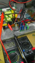
There was nothing wrong during initial calibration, everything went smooth for both channels. Modules was already mounted on heatsinks. Problems came after connecting with the DAC. I've measured DC it was OK and few minutes after DC apeared (about 2-3 volts) on left channel. I suspected input pair but it was R20, replaced it, calibrate again DC below 1mV, on 22 ohm resistor 4,00 volts by trimer TR3. Between TP1 and TP2 122mV, checked one of the jfet current it was 2,67mA. After couple of minutes DC apeared again and this time it was R16 10 ohm. Replaced this one also. All the time right channel was OK.
Then during hum and buzz troubleshoot, on the right channel DC apeared and after that I saw little flash(heard it too). It was R19. I will replaced this one later. But beyond that
 .
.Yes, I noticed. In any case, you have LC's attention now... I am sure that will help more,...If you didn't notice there is already 10R smd between input ground lead and ground(speaker gnd and power gnd) on the pcb.
Andrej,
What is the dimension of your VSSA aluminum case? Internal and external.
Thanks,
Fred
What is the dimension of your VSSA aluminum case? Internal and external.
Thanks,
Fred
Very good since this Alu case is prepared for VSSA and SMPS400.
OK, if there will be at least 5-8 more GB members for this kind of chassis, than my supplier can start with his minimum starting amount of 10 pcs.
LC, what parts are in chasis deal? Predrilled you said, for RCA and speaker bindingposts too? Are they included then? Your hidden on/off switch...IEC power input. If only predrilled we need specific data which parts, dimensions vary. Can you make 1 post with all chasis data?
To make it easier (I hope i did not miss anyone. If yes, you can add to this list). I can count already 11 so the show can start
Lazy Cat - 2 (not sure if anyone below already included in this number)
pinnocchio - 1
CaféNoir - 3
Joachim Gerhard - 1
vitalica - 3
metallicus69 - 1
Lazy Cat - 2 (not sure if anyone below already included in this number)
pinnocchio - 1
CaféNoir - 3
Joachim Gerhard - 1
vitalica - 3
metallicus69 - 1
Miksi please step by step. First make both channels to work normally as guided by installation manual, meaning all DC and bias conditions are OK.
Than I will give you info abot grounding.
Please also check output conditions of your DAC/preamp that there is no DC present.
Burn out 10 Ohm VAS emiter resistor indicates too much DC at the input or that one of input BJT is broken (C-E shorted).
Than I will give you info abot grounding.
Please also check output conditions of your DAC/preamp that there is no DC present.
Burn out 10 Ohm VAS emiter resistor indicates too much DC at the input or that one of input BJT is broken (C-E shorted).
Very good guys I'll organize group buy for Lakner Oné Alu cases. More info soon.
If you want feedback from 80% of the despatches of the kits, please arrange a GB of the required capacitors. Else, from the posts, only 10% will complete the assembly!
Shipping the caps is expensive (I am already doing it for a couple people), and there is not much agreement on the caps anyway ...If you want feedback from 80% of the despatches of the kits, please arrange a GB of the required capacitors. Else, from the posts, only 10% will complete the assembly!
Seriously, anyone else can organize a GB for capacitors, why should LC have to do all the work?
If you want feedback from 80% of the despatches of the kits, please arrange a GB of the required capacitors. Else, from the posts, only 10% will complete the assembly!
I got all the capacitors from Mouser and for the power supply (Hypex) the only one I'm missing are the 1500uF 200V but will import them from RS components in the UK.
I could potentially order the amp caps for all the ones missing them but shipping from Canada could be expensive, still not more than Mouser that charges 20$ for shipping... Could save if shipping using padded envelope and more expensive if using a small boxe. Caps would be the ones specified by LC and only those ones... I'd like to see a list of interest for now before I commit to this.
Do
Miksi please step by step. First make both channels to work normally as guided by installation manual, meaning all DC and bias conditions are OK.
Than I will give you info abot grounding.
Please also check output conditions of your DAC/preamp that there is no DC present.
Burn out 10 Ohm VAS emiter resistor indicates too much DC at the input or that one of input BJT is broken (C-E shorted).
Ok, R19 replaced and (for now) both channels are stable with DC about 1mV and voltage across 22ohm of 4 V. Driver current about 12mA, jfet current about 2.7mA. Tested for couple of hours. Only alu box is connected to safety earth lead, the rest is floating. Hypex supplies are connected thru one of their montage holes to the box. Driver transistors holes are also isolated from alu box.
DAC output Lch -0.7mV, Rch 0.1mV.
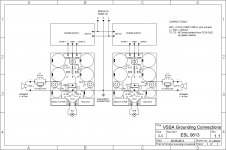
What is left to do is proper grounding to eliminate hum and buzz.
Attachments
Last edited:
I got all the capacitors from Mouser and for the power supply (Hypex) the only one I'm missing are the 1500uF 200V but will import them from RS components in the UK.
I could potentially order the amp caps for all the ones missing them but shipping from Canada could be expensive, still not more than Mouser that charges 20$ for shipping... Could save if shipping using padded envelope and more expensive if using a small boxe. Caps would be the ones specified by LC and only those ones... I'd like to see a list of interest for now before I commit to this.
Do
Actually, disregard this post... Way too many projects for the summer to get into this.
Do
Exactly. Now when everything is working properly do nothing. Wait for my next post which will also be very important for the rest of GB members.What is left to do is proper grounding to eliminate hum and buzz.

- Home
- Vendor's Bazaar
- VSSA Lateral MosFet Amplifier