why not use one module SMPS 1200A180, with two boards VSSA?Hi Axel
Very good choice of components.
Yes, DC sense module will work with VSSA and SMPS1200A180, for stereo you would need two.
PM sent.")
because the power supply, with a margin of 2 to the power supply module.
Anyway you'll need two DC sense modules, for each VSSA channel one DC sense.
these modules I are, but as they are both connected to the same SMPS 1200A180?
I built a 20v +/- version of it recently going wih shaan's layout. i felt the amp was underbiased even with 15k resistors reduced o 12k, the heatsinks were cool to the touch and sound 'weak'. so i brought the vas resisors down to 7k ohm. mosfet bias increased- another diode in the string and 470ohm resistor taken out. and feedback resistor values changed from 2.2k to 6.6k i needed more gain anyways.
sounds much better now and still very stable.
biggest change was the feedback resistor- i was able to compare the sound at same volume to the other channel still with 2.2k and higher feedback made it sound more dynamic and tilted the focus to bass.
i also shorted 100ohm to mosfets and the sound was better but dc offset skyrocketed.
what else should i try and what's up with the vas resistors? i was told that 12k would be low enough for 16v psu but clearly that's underbiasing it.
mosfet bias increased- another diode in the string and 470ohm resistor taken out. and feedback resistor values changed from 2.2k to 6.6k i needed more gain anyways. sounds much better now and still very stable.
biggest change was the feedback resistor- i was able to compare the sound at same volume to the other channel still with 2.2k and higher feedback made it sound more dynamic and tilted the focus to bass.
i also shorted 100ohm to mosfets and the sound was better but dc offset skyrocketed.
what else should i try and what's up with the vas resistors? i was told that 12k would be low enough for 16v psu but clearly that's underbiasing it.
No fuzz about VAS resistors. Maybe you should try VSSA's successor from the other thread of mine.what else should i try and what's up with the vas resistors?
Guys,
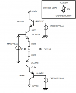
When you are bored, you should really try the "Cascoded output" version of the VSSA. I did an all-BJT Cascoded version of this wonderful little amp and it sounds more open and transparent than the original BJT-VSSA.
My goal is then make a V-FET Cascoded VSSA in order to have a fast, dynamic and transparent amp.
Then, maybe and "all cascoded" amp...
Cheers,
M.
Attachments
So you will have only about +/- 25.5 Volts available for the output to swing to even though the supply is at +/- 32 V!
Below about 35 watts into 8 ohms I guess.
Hi,
I am still in the phase of study and experiment but I have not confirmed yet what is the power behavior with the scope. Anyway, It doesn't worry me because:
1) The goal is to have a better sounding amp.
2) I have sensitive speakers so there is still plenty of power.
3) I have ready to go power supplies with +/-42VDC, +/-60VDC and +/-72VDC, waiting for some action.
The bigger one will have 3 cascoded VFETs pairs per channel, if all goes well...Cheers,
M.
So you will have only about +/- 25.5 Volts available for the output to swing to even though the supply is at +/- 32 V!
Below about 35 watts into 8 ohms I guess.
Quick update. Many experiments as time allowed and many transistors that went to semiconductor heaven.
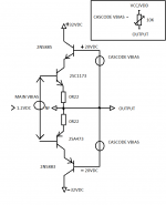
I got it wrong at first. The lower BJT is the one that makes the voltage swing and the upper "cascoded" BJT provides the current gain, apparently...anyway, I am making experiments with incremental Vbias for the base of the "cascoded": now +/-20VDC and 0.6 lower for the collector of the lower unit. If everything goes OK, I will continue to increase the Vbias until the "cascoded" BJT stops working and/or the amp becomes unstable...I guess around +/-25VDC or even more, depending on the transistor chosen.
It sounds wonderfully dynamic, extended, open and detailed to me, but I can be biased
If anyone thinks about a clever way to bias it or other, just post.
This is a very recommended experiment.
Attachments
- Home
- Vendor's Bazaar
- VSSA Lateral MosFet Amplifier