bequerel said:Guys,
How do you calculate the voltages when using a CCS to feed a VR150 tube?
Let us say that the VR150 needs 200V to work correctly and ignite, and that the CCS needs a voltage drop of minimum 30V to work.
Can I just make sure that my power supply delivers minimum 230V (220V + 30V) to the CCS?
Yes, this is why it is VR Safety for Dummies. The CCS will, in essence, figure out how much voltage to drop for you. Just be sure the CCS has a proper heatsink, and you can feed it anything you like.
As I said, use a VR tube with a source follower, such way you keep current through it relatively stable, also you can implement a RC filter from it to gate, so no shunting capacitor is needed. I use such approach in several models of my amplifiers, it works fine, and tubes are glowing many years without need to replace them.
dsavitsk said:
Yes, this is why it is VR Safety for Dummies. The CCS will, in essence, figure out how much voltage to drop for you. Just be sure the CCS has a proper heatsink, and you can feed it anything you like.
Cool, thanks!
Hey Guys,
I want to use a VR150 to regulate 2nd screen grid on a 6P15P and 6GK5 plate voltage in an RH84 SE amp. I found the formula to derive the load limiting resistor. But I still have a couple questions. First the data sheet says input voltage minimum is 180 volts but doesn't spec a maximum. Can the source voltage be at B+? In this case 300 volts? Second, the mean amperage is 22.5ma. Two 6P15P grids and two 6GK5 plates total 32ma. Will this allow enough range that it won't overamperage the tube and cause arcing? And lastly the bypass cap mentioned earlier is to shunt noise? And should be an electrolytic?
Thanks, Kevin
Kevin, I have a little test rig here that I use to quickly check VR tubes. Off load voltage is 330v and doesn't give any problems with any good VR tubes (it finds the ones that have had their gas leak out though).
If you are concerned about the current carrying capability, get the VR150/30 version, it is rated at 30mA continuous.
Gary
If you are concerned about the current carrying capability, get the VR150/30 version, it is rated at 30mA continuous.
Gary
Hi all,
Quick ?,
I am rebuilding my RH84 (EL84 Pentode SE) and am considering regulating G2.
I have never used Gas tubes before, only zeners but have a VR150. So, I am thinking about the VR150 and was wondering if there would be a problem using it with SS rectification for the B+.
Makes no difference. If you've used Zeners, VR tubes are no different. Just make certain you don't connect a capacitor in parallel. Being that it operates by means of a glow discharge, that means a negative resistance characteristic the Zener doesn't have, and negative resistance means possible oscillation. Also, the noise that Zeners make is more objectionable than that of VR tubes.
I did read somewhere that they do not like being turned on and off and on again quickly.
They don't. The spec sheets usually tell you to make sure they operate for ~20 minutes. Otherwise, you could compromise the accuracy of the regulation. I use 'em for voltage references:
Le Renard Screen Regulator
Works like its SS counterpart, and have not required any adjustments since this began service five years ago. Future iterations won't require a variable resistor, since once set, it hasn't been touched at all. In this case, the VR tube isn't under any sort of load, doesn't need to pull any big currents, and a simple RC LPF is really all you need for noise protection.
The pentode half of that dual requires special attention to layout details and stoppers since it's a high gain pent. Since the screen voltage required is just 150Vdc, the Vhk ratings aren't stressed, and so don't require a separate heater xfmr with a voltage lift to keep from exceeding a Vhk limit.
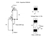
I tried feeding a VR150 with a DN2540 and then with an IXYS 10M45. Both worked OK. For 58mA (36mA load plus 22v for the VR150) with a dropper resistor the B+ before the resistor is 200v. With the IXYS it's 180v. With the Supertex it's 172v. In all cases the VR150 lights up.
The stated strike voltage is 185v with a resistor. In both cases, with the active devices, the strike voltage is less than that.
Can anyone explain this?
The stated strike voltage is 185v with a resistor. In both cases, with the active devices, the strike voltage is less than that.
Can anyone explain this?
Explain what? The voltage drop across the upper element during normal operation has nothing to do with striking voltage. Striking voltage is the applied voltage at which the regulator begins to conduct, thus reducing the applied voltage. This tells you nothing about the voltage on the other end of the resistor/CCS.
Explain what? The voltage drop across the upper element during normal operation has nothing to do with striking voltage. Striking voltage is the applied voltage at which the regulator begins to conduct, thus reducing the applied voltage. This tells you nothing about the voltage on the other end of the resistor/CCS.
I think it's fair to ask for an explanation of how to use VR tubes with a CCS - there's nothing in the data sheets or application notes about this since they were written before such devices were used. We know the voltage on the load which is 150v in the case of a 0D3, and we have the "headroom" needed for a VR to strike with a resistor, which is 35v above 150v.
My question is what headroom do you need with a CCS? In previous posts it's stated "apply any voltage to the CCS and it will do it's job", but is there a minimum voltage that needs to be supplied to the CCS above the 150v? And does this headroom change for one or two devices?
Attachments
Any CCS will have a minimum voltage for normal operation, but remember that a non-conductive VR will take very little current (almost zero) so the CCS will probably have very little voltage drop across it at first. However, once the VR strikes the CCS must be able to supply the required current.
Your question is actually about CCS, not VRs!
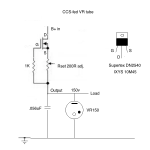
If the CCS drops too much voltage for VR striking but is OK when running normally then you can add a resistor and diode to fix this situation, provided that the supply rail is above the strking voltage. The CCS feeds the load, whatever that is. A high value resistor (few hundred k ish) feed the VR and ensures striking. A rectifier diode connects the two junctions together, arranged so that it is reverse biased before striking but forward biased once the VR pulls its side down. You can see a similar arrangement here, although for different reasons.
Your question is actually about CCS, not VRs!
If the CCS drops too much voltage for VR striking but is OK when running normally then you can add a resistor and diode to fix this situation, provided that the supply rail is above the strking voltage. The CCS feeds the load, whatever that is. A high value resistor (few hundred k ish) feed the VR and ensures striking. A rectifier diode connects the two junctions together, arranged so that it is reverse biased before striking but forward biased once the VR pulls its side down. You can see a similar arrangement here, although for different reasons.
Hey All,
I want to use a VR150 in My RH84 to regulate screen voltage for 6P15P's. I found this formula; Source voltage - regulated voltage/ mean current + load current = series resistance. So for the RH it would be 300 - 150 / 22.5ma + 9ma = 4.76ohms? Does that sound right? And you all seem to be saying the tube needs a bypass cap? .1uf @ 300volts? Also, The current window for this tube is between 5 and forty ma. Is the 9ma grid current of the 6P15P's too low for the tube to work properly? Or do I have to add a parallel resistor with the load to get to the mean current of 22.5?
I want to use a VR150 in My RH84 to regulate screen voltage for 6P15P's. I found this formula; Source voltage - regulated voltage/ mean current + load current = series resistance. So for the RH it would be 300 - 150 / 22.5ma + 9ma = 4.76ohms? Does that sound right? And you all seem to be saying the tube needs a bypass cap? .1uf @ 300volts? Also, The current window for this tube is between 5 and forty ma. Is the 9ma grid current of the 6P15P's too low for the tube to work properly? Or do I have to add a parallel resistor with the load to get to the mean current of 22.5?
Hey All,
I want to use a VR150 in My RH84 to regulate screen voltage for 6P15P's. I found this formula; Source voltage - regulated voltage/ mean current + load current = series resistance. So for the RH it would be 300 - 150 / 22.5ma + 9ma = 4.76ohms? Does that sound right? And you all seem to be saying the tube needs a bypass cap? .1uf @ 300volts? Also, The current window for this tube is between 5 and forty ma. Is the 9ma grid current of the 6P15P's too low for the tube to work properly? Or do I have to add a parallel resistor with the load to get to the mean current of 22.5?
You have an error in the maths...
300V - 150V = 150V
22.5mA + 9mA = 31.5mA
150 / 31.5mA = 4761 ohms (use 4.7k ohms, 5 watt minimum - 10 watts would be good)
(clue - you are using milli-Amps, not Amps).
But why choose 22.5mA? You don't need to reach the average current level. Wouldn't 10mA though the regulator give the same result, save power and wasted heat and also give longer life, ?
(300V - 150V) / (10ma + 9ma) = 7984ohms (so use 8.2k ohms, 3 watt minimum - 5 watts would be good)
Hey Guys,
I used the 8k series resistor. but I could only get 2ma for each screen. And the result is only 15ma draw on the 6P15P. I changed to a 6.8k series resistor with no change. Still only 2ma to each screen grid. What am I doing wrong? When I had just a 10k resistor between B+ and the grids the tube drew 28ma so I'm pretty sure the problem is in the regulator circuit.
I used the 8k series resistor. but I could only get 2ma for each screen. And the result is only 15ma draw on the 6P15P. I changed to a 6.8k series resistor with no change. Still only 2ma to each screen grid. What am I doing wrong? When I had just a 10k resistor between B+ and the grids the tube drew 28ma so I'm pretty sure the problem is in the regulator circuit.
- Status
- This old topic is closed. If you want to reopen this topic, contact a moderator using the "Report Post" button.
- Home
- Amplifiers
- Tubes / Valves
- VR150 use