Hi, ive built a phono amp and a pre amp.
Im running my CD player direct into the pre-amp as an output stage with the volume control before the power amp.
All is well.
The phono amp is fine but a little quiet so i tried putting it through the same pre amp stage as the CD player.
When i do this the volume just swings all over the place, loud/quiet/bit loud/silent/loud etc etc.
This is the pre amp stage, the volume controll is after this, there are 1k grid stoppers on the input.
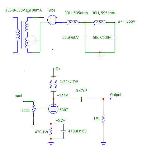
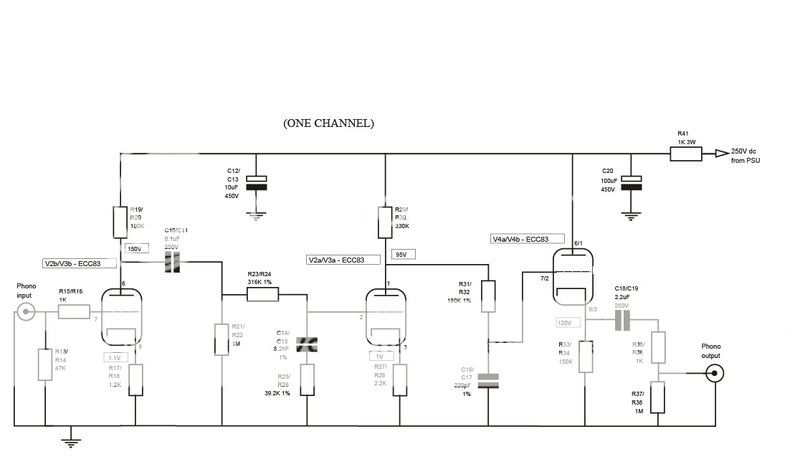
This is the phono stage
they both work fine independantly but feeding the phono into the 5687 results in the mad volume fluctuations.
I tested the phono outputs with nothing connected, they have fluctuating DC varying from 0v to 0.05v. I dont know if thats normal or not?
Im a bit new to all this so its got me proper stumped.
Im running my CD player direct into the pre-amp as an output stage with the volume control before the power amp.
All is well.
The phono amp is fine but a little quiet so i tried putting it through the same pre amp stage as the CD player.
When i do this the volume just swings all over the place, loud/quiet/bit loud/silent/loud etc etc.
This is the pre amp stage, the volume controll is after this, there are 1k grid stoppers on the input.
This is the phono stage
they both work fine independantly but feeding the phono into the 5687 results in the mad volume fluctuations.
I tested the phono outputs with nothing connected, they have fluctuating DC varying from 0v to 0.05v. I dont know if thats normal or not?
Im a bit new to all this so its got me proper stumped.
Motorboating. You need to decouple the first stage from the second two. Use a separate RC circuit to the first stage's plate resistor istead of counting on R41 for all three stages. It's OK (and maybe preferable) to feed the second stage and its cathode follower from the same rail, but the first stage needs a rail of its own.
Yes, they share the same power supply.
The PSU is designed to power a phono and a pre (just not this pre).
Both the phono and pre have their own 1k/100uf RC filter inside there cases to isolate them from each other and the PSU. (the power supply is cased seperately)
I normaly run my CD players dac chip pirect into the 5687, still with the 1k grid stoppers.
I can have both units working at the same time, no problem.
Issues only arrise when i link the 2 together.
Ive been given a couple of suggestions to try on another forum, but all suggestions welcome, 2 brains are better than 1 and all that")
Thanks.
The PSU is designed to power a phono and a pre (just not this pre).
Both the phono and pre have their own 1k/100uf RC filter inside there cases to isolate them from each other and the PSU. (the power supply is cased seperately)
I normaly run my CD players dac chip pirect into the 5687, still with the 1k grid stoppers.
I can have both units working at the same time, no problem.
Issues only arrise when i link the 2 together.
Ive been given a couple of suggestions to try on another forum, but all suggestions welcome, 2 brains are better than 1 and all that
Thanks.
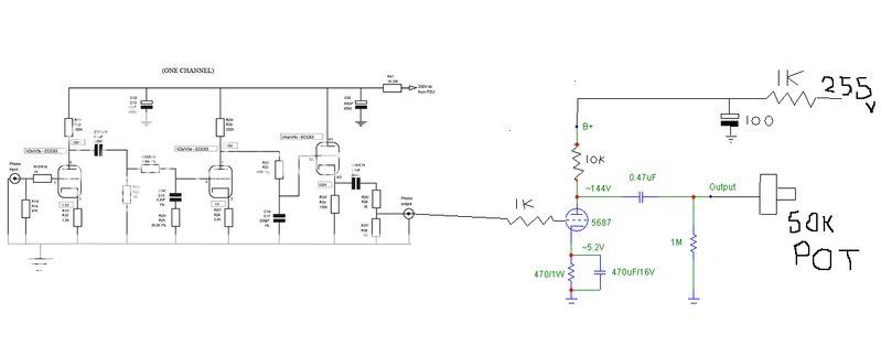
graeme uk said:This is how they are linked.
Forgive the shoddy 'paint' skills
If your voltage values on the phono stage are accurate, then an entire single channel draws approximately 2.5ma of current. The 5687 line stage draws approximately 11ma of current per channel, quite a difference.
When you drive the line stage directly from the phono stage, you have full gain and any rumble and/or record warp will certainly push the 5687 to large low frequency swings which could dip the supply voltage enough to cause some supply motor-boating.
I would be inclined to put the volume control back in front of the 5687 line stage for a start. If the power supply circuit in your original drawings is quiet when feeding the line stage directly (sans the 1K resistor in your above drawing), I would delete the resistor and again drive the 5687 line stage directly.
Second, I would calculate a voltage dropping resistor for each channel of the phono stage based on the desired voltage drop against 2.5ma of current. If your supply has a measured output of 255 volts with both channels of the line stage active, I would try and drop to no more than 240 volts. This would calculate to 255-240 = 15 divided by 2.5ma (0.0025) = 6K ohms. A 6.2K is a standard value and should work fine. You can also do the same for "inside" the phono stage as suggested earlier.
Regards, KM
graeme uk said:Ah.
I forgot the power supply.
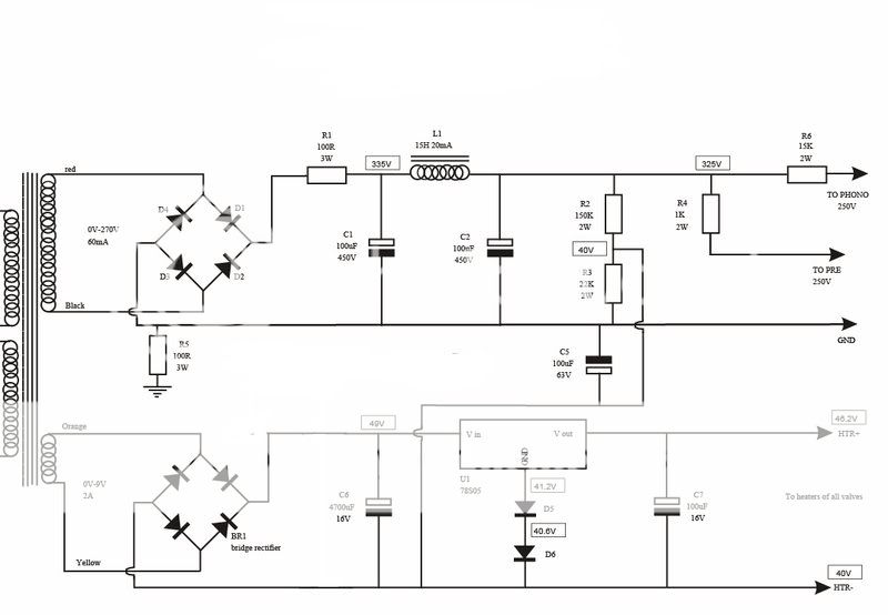
Im not using the power supply at the top of the thread.
Im using this.
Hi Graeme,
Well, that's a bit different from the initial supply. A few comments:
1- the filter choke is below the required current rating. I would replace it with a something rated for at least 50ma and 20H or more would help.
2- the 1K dropping resistor implies 75ma of current for the line stage with the listed voltages. A 3.3K would be more in line if the line stage is the same as above, i.e., 11ma of current per channel.
3- R5 in the supply is between the negative supply rail and ground. Is this chassis ground? How does this relate the the ground(s) shown in the phono and line preamp? A single point ground should be used.
Beyond this, I would still suggest moving the volume control before the line stage. I would also check to see if you have any bad filter caps. You show fairly large ones in the supply and preamp circuits...
Regards, KM
Ok, my PSU is a clone of the design above so ill answer in order.
1, im not sure on my choke specs, i was given it as one that would do the job. Ill check it.
2, ok, ill change it. This PSU is designed for the phono i built but not for this pre stage.
3, yes, r5 goes to mains ground. All the grounds in the phono and pre go to the PSU ground, therefore they are all 100r above mains earth.
Ill try and explain why the volume is after the 5687.
I have a PS1, i removed the output stage. Direct from dac chip to passive pre/power amp it was too quiet and didnt sound that great.
I fed the dac chip into the 5687 and it sound great. This then goes to my passive pre so the volume is after the 5687.
My phono stage is also a little quiet so i thought i'd try it through the 5687 stage. I disconected the dac chip and connected the phono instead.
If the phono sounds better running through the 5687 i will use the 5687 as a pre-amp rather than the outpuit stage it currently is.
If i do that, the volume control will then be before the 5687.
Its been suggested i need a 100k resistor from the 5687 input to ground (simulating a volume pot i guess) If that works i can see how it sounds. If it sounds nice ill replace the 100k resistor with the volume pot and use the 5687 as the active pre.
Does that make sense?
- Status
- This old topic is closed. If you want to reopen this topic, contact a moderator using the "Report Post" button.
- Home
- Amplifiers
- Tubes / Valves
- Volume swinging problem