I’ve recently (almost) finished my amplifier, and I’m having trouble with the volume pot. I wasn’t going to add one, but my current phono pre amp doesn’t have one, so why not…
It’s an Audio Note 100k log volume pot, so not some cheap thing. Under normal circumstances it is pretty scratchy sounding particularly in the left channel only when adjusting the pot. I normally leave it at full volume except for vinyl listening, and bias checking, so the scratching sound is not too big of a deal. Today I was listening for about two hours, and noticed a scratchy sound; I was listening with a low input volume, and the scratchy sound was pretty loud. I adjusted the volume pot slightly, as I immediately suspected the pot, and got a very loud noise on the left channel. No abnormal temperatures, voltages, or bias anomalies.
Did I get a defective part, or is there another likely explanation?
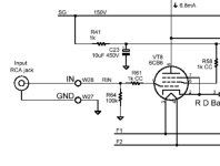
I have the wiper of the pot going to R61, and the full resistance of the pot basically replaces R64

Thanks
It’s an Audio Note 100k log volume pot, so not some cheap thing. Under normal circumstances it is pretty scratchy sounding particularly in the left channel only when adjusting the pot. I normally leave it at full volume except for vinyl listening, and bias checking, so the scratching sound is not too big of a deal. Today I was listening for about two hours, and noticed a scratchy sound; I was listening with a low input volume, and the scratchy sound was pretty loud. I adjusted the volume pot slightly, as I immediately suspected the pot, and got a very loud noise on the left channel. No abnormal temperatures, voltages, or bias anomalies.
Did I get a defective part, or is there another likely explanation?
I have the wiper of the pot going to R61, and the full resistance of the pot basically replaces R64

Thanks
Sounds like thunder, correct? It seems there is some direct current present across the wiper, ie the center tap of the potentiometer, originating from the source or the tube’s grid. Any potential on the grid stop resistor will cause a small current to flow. A signal coupling capacitor between the wiper and R61 is one remedy.
Last edited:
DC seems likely; although I haven’t attempted to measure anything yet, sound with no signal has to be originating somewhere. It would seem to make sense that it’s coming from the amp, as it’s scratching just the same with no input. It is also the same from my music streamer, or from the DSP output of my subwoofer.
All open construction pots or switches will get this over time, even if just sitting on the shelf.
Spray a small amount of deOxit D5 into it, and exercise several times. Repeat if necessary.
Nothing else will work as well.
https://www.amazon.com/Hosa-D5S-6-DeoxIT-Contact-Cleaner/dp/B00006LVEU/ref=asc_df_B00006LVEU/
Spray a small amount of deOxit D5 into it, and exercise several times. Repeat if necessary.
Nothing else will work as well.
https://www.amazon.com/Hosa-D5S-6-DeoxIT-Contact-Cleaner/dp/B00006LVEU/ref=asc_df_B00006LVEU/
Not too keen on a coupling cap, but could try it. Would a high value (~1M) resistor from the wiper to ground help?A signal coupling capacitor between the wiper and R61 is one remedy.
The pot is brand new… not sure if it’s serviceable, but I can give it a try. I’ll certainly use the deOxit before anything else.All open construction pots or switches will get this over time. Spray a small amount of deOxit D5 into it, and exercise several times.

This kind of stuff sits around on the shelf in the open air for a long time before being sold.
It isn't properly packaged by the mfr for long term storage. It really should be considered perishable.
When you spray the D5, set it on the lowest spray setting, shake, and spray inside each section as briefly as possible.
Then turn the pot up and down all the way several times, and give it a try. Repeat if necessary.
Use as little as possible each time. If it really is from recent production, just one spray may do it.
Old stuff from the 50s-60s can take several sprays but will usually work ok, if not severely corroded.
Last edited:
Yes. If the wiper loses contact, the grid has no DC path to ground. That causes the loud noise.Not too keen on a coupling cap, but could try it. Would a high value (~1M) resistor from the wiper to ground help?
Ed
Not too keen on a coupling cap, but could try it. Would a high value (~1M) resistor from the wiper to ground help?
I made my intial response under the impression the potentiometer was new, so I’m glad to read it is. I would draw a schematic and calculate the time constant if I was home, but the first approach I would investigate would be as follows: After the input RCA jacks would be the input RFI lowpass filter, then the signal coupling cap, then the pot, then a ground reference resistor and the series grid stopper leading to the tube’s grid. This setup assumes there is a residual DC from the source, but it could be something to do with the grid itself.
should've left (the original as-per-design) R64 in place.... see post No. 7I have the wiper of the pot going to R61, and the full resistance of the pot basically replaces R64
View attachment 1288687
Thanks
The grid is leaking current directly into the POT.
Any small change in the wiper arm contact resistance as it is turned results in a noise that is equal to ...
Ileak * Rwiper-delta= Vnoise.
So a 1uA leak current with a wiper contact resistance change of only 1K during movement results in a 1mV noise right at the tubes grid.
In real life there is often far more than a 1K contact resistance change during wiper movement.
Putting R64 back may well help but you still may have some noise left. Try and see if it is ok with R64 back if not a coupling cap may be needed.
Any time you have DC in a audio pot even tiny amounts noise is far more likely much sooner as the wiper contact resistance varies while moved. Yes cleaning it may well make it go away.
However if there is DC in the audio pots the noise will return much sooner.
This is a common symptom of older equipment that have leaking coupling capacitors.
The leakage currents that results in the pots make them become very noisy very often.
At the risk of becoming gloomy DC current in any contact with any oxidation produces a nonlinear diode action and will add distortion to the audio path. This is part of the reason audio pots have a bad name.
Thanks for the thorough explanation. I tried it again today while the deOxit is on order, and the problem is worse. I did figure out it’s both channels; I’m just closer to the left speaker when adjusting. I don’t think I have any leaking capacitors, as they’re all new, but it’s possible. I did order another set of driver tubes, as I did fry one (or just had a bad one) when initially testing the amp.
Tomorrow I will bypass the pot to test if I have a tube problem, as I can live with my digital source until the problem is resolved if it’s just the pot.
I will also add R64 back in as suggested.
Tomorrow I will bypass the pot to test if I have a tube problem, as I can live with my digital source until the problem is resolved if it’s just the pot.
I will also add R64 back in as suggested.
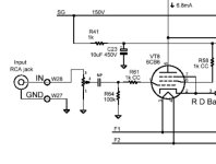
This will provide a ground reference and grid current path, while keeping the screen current off the wiper. It would be best to use a capacitor that is not polarized, preferably flat stacked film or a NP (non-polar) electrolytic. An audiophile radial film capacitor can lead to noise pickup and instability in this position.


Thanks! If the problem persists, I will be likely trying this. I found some deOxit locally, so I tried it on the pot this morning and added R64 back in. I had to use 220k resistors for now, as it’s all I had in a decent quality resistor.This will provide a ground reference and grid current path
There is some noise near the middle of the pot, but much better than it was. Been running the amp for an hour now, and the bad noise it was making hasn’t shown up. Needs more testing to be sure.
That is the correct way to do this. Deriving the grid voltage through a pot, especially via the wiper is asking for trouble. A 2.2uF non polarised cap will give you all the bass you need with R64 at 100K. It also protects against any source device that might have a DC offset which would get amplified by the valve.This will provide a ground reference and grid current path, while keeping the screen current off the wiper. It would be best to use a capacitor that is not polarized, preferably flat stacked film or a NP (non-polar) electrolytic. An audiophile radial film capacitor can lead to noise pickup and instability in this position.
View attachment 1289583
Thanks guys. I have a few more things I need to try as the problem returned after a couple hours of run time with 220k grid leak resistors in place. It may be a cold solder joint, or a bad driver tube as well; I’m starting to suspect the scratchy pot and this noise are two separate issues, although they sound the same.
Hi DuRWooDJBL,Thanks guys. I have a few more things I need to try as the problem returned after a couple hours of run time with 220k grid leak resistors in place.
It’s unfortunate that this problem returned, but we’re all here to brainstorm in an effort to try and help.
It may be a cold solder joint, or a bad driver tube as well; I’m starting to suspect the scratchy pot and this noise are two separate issues, although they sound the same.
That could be it. One thing which I find telling is that the problem returned after hours of runtime, because normally leakage through a capacitor reduces with an increase of time in which it is being charged. I would start with re-seating the tubes in their sockets, and if that does not reveal the cause it may take swapping the tubes with new ones, one-by-one. If you do not have extra tubes on hand, you could reflow the solder joints. I reflowed every joint in a television once to fix a progressive problem with the picture cutting out.
If you have an oscillioscope with appropriate rated probes it could find this audible problem rather quickly by making it visible.
- Home
- Amplifiers
- Tubes / Valves
- Volume pot noise