I'm still working on my guitar amp(s) and have found that one of my biggest problem is noise in the form of hiss.
I've got my second build down to what I consider reasonable. A friend who helps em evaluate the amp considers it much better than his Fender Baseman.
However in my quest, I have started to wonder how much noise a tone-stack (or volume control for that matter) introduces into an amp. And, does the potentiometer type make any difference? That is to say, are there some potentiometers that are quieter than others (given the same resistance).
In the case of the amp I'm working on the tone-stack is after the first gain stage. I can remove the first tube and the hiss starts increasing after I hit the noon position on the volume control. If I put the first tube back in, there is more hiss associated with it.
Is there any kind of standard for the procedure of measuring noise in amplifiers?
So far the best tool I've found is Audio-Tester in the spectrum analyzer mode as it allows me to see the noise floor as well as peaks and noise profile vs frequency.
Different kinds of resistors will have a big impact on noise. Carbon composition are noisiest. Resistors typically make a hissing sound (like you described). Resistor temperature also plays a part in noise. Overrated resistors (in terms of watts) will reduce noise slightly although changing the type will have the biggest effect. Pots being resistors (typically carbon comp) can add noise. The noise will be cumulative, targeting only the tone stack isn't going to have that much of an effect by itself.
What amp is this and what kind of resistors are in it?
What amp is this and what kind of resistors are in it?
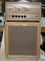
The amp is a high gain top boost lead amp which is taylored for small venues and studio use (only 10W).
The design evolved from the Train Wreck Liverpool design (info from The Amp Garage) but has been modified considerably.
The TrainWreck design uses the tonestack following the first gain stage. Since most of the gain of the amp follows the tonestack, noise is an issue.
I'm currently using Carbon Film pots, but am wondering if more expensive Conductive Polymer pots would contribute noticably less noise.
Attachments
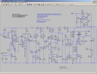
I'm no guitar amp expert, but that is a strange circuit. It uses high gain valves, then throws some of the gain away but in the wrong place (before most of the gain). U1B is a high impedance cathode follower, so the tone stack has to use high value pots so you get more thermal noise than necessary. Then you throw away signal in a potential divider formed by R101 and R2 at the second stage grid (BTW have these resistors been swapped -everywhere else 27K is used as a grid stopper but here it is the grid leak).
My guess is that the signal at U2A grid is not much higher than the input at U1A grid, so both valves contribute to overall noise. You have enough gain that even thermal noise from R2 will probably be audible. You need to get the gain distribution right: more before the tone stack and less after U2A. Try removing C7.
You might be getting noise from the zener at D7, although I assume that under normal conditions this is not supposed to conduct.
Guitar Amps are strange animals.
My understanding is that it is common to use excesive gain, then throw part of the signal away. This is done to enhance harmonic distortion at moderate signal levels.
The zener is for protection and should never conduct (or at worst case during power up).
My understanding is that it is common to use excesive gain, then throw part of the signal away. This is done to enhance harmonic distortion at moderate signal levels.
The zener is for protection and should never conduct (or at worst case during power up).
I am familiar with the trainwreck series of amps. And yes that kind of thing is normal for guitar amps. It's not so much about clean voltage gain as it is shaping and overdriving successive stages with too much voltage input.
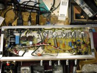
May we get a gut shot to investigate further? Carbon pots could be adding noise and its possible that changing them for plastic or other material will reduce it. Do you have any other carbon resistors in the amp?
It's possible that D9 is adding noise in. It's typical (and normal) for guitar amps to have a 10k in series with the diode to limit current going through it if (more like when) the grid gets driven positive.
The first thing to do is short the grid of U2B to ground and measure the hiss at the output. The remove the short, short the amp input, and measure the noise at the output again, first with the volume turned right down and then with it full up. |Report back with those figures and we'll have something to go on.
By the way, the values of the tone stack resistors are not that high and the noise they create should be negligible.
Cheers
Ian
By the way, the values of the tone stack resistors are not that high and the noise they create should be negligible.
Cheers
Ian
The amp is all metal film resistors. I've recently started changing them to 2W even if they don't need it for power dissipation just to see how it effects the amp.
I'll have to pull the amp back apart to get the gut shots as I had it put together to take to the Spartanburg Guitar show (BEE-3 Vintage Guitar Show) in SC tomorrow to get some (hopefully) unbiased opinions.
I'll have the gut shots and frequency sweeps a little later tonight.
I simulated the tone-stack in LTSpice and it looked like about 100K with all controls at noon.
Last edited:
I've recently started changing them to 2W even if they don't need it
Tube amps are pretty robust but be aware that more equipment is broken by unnecessary 'fixing' than most of us care to remember.
That's why they say, 'if it ain't broke, don't fix it'.
w
I should have said " ... if they don't need it for power dissipation/reliability purposes".
If it is broke, fix it.
If it isn't broke, modify it.
Changing the resistors was to see if I could measure a difference in noise between resistor sizes. It made a difference in some locations (where large resistance values were used).
Photos are :
1. Gut Shot,
2. Tonestack Disconnected,
3. Tonestack connected and all controls at noon except volume set to min,
4. ... vol set to mid,
5. ... vol set to max
Measurements were made with no input to the amp which has a shorting input through a 68K resistor.
Plots are from Audio Tester V3.
Sound card is M-AUDIO 192.
Input has no attenuation and is taken off a 8 ohm resistive load.
Attachments
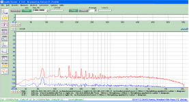
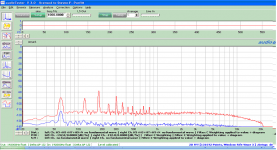

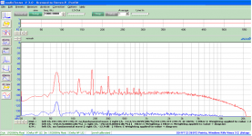
Your noise floor is pretty good. The 60 Hz and 120 Hz peaks are to be expected from the mains. I would think a noise floor at -50 would be good. How bad does the hiss get?
Is it possible the speaker or speaker wiring is bad? Those graphs are actually pretty good even with the tone stack connected.
Are the power supply capacitors hooked up as diagramed? If so they are backward (in a sense) because the effect of smoothing is cumulative. It doesn't show the plate supply having any (usually is the reservoir) either. Zener D7 could be a culprit although it doesn't seem likely. If you have an 6v zeners replace D7 with two of these (6v zeners are the quietest of all zeners).
Just some ideas, hope they help
C17 is the plate filter cap.
D7 does not make any difference (it is out right now as I use the standby switch).
Thanks, keep the suggestions coming.
I'm not sure the amp is that bad, I'd just like to improve it. I can hear the hiss 4' from the speaker with the volume set to noon, so I presume it is too loud considering it is only 10 watts.
4mV in drives it to clipping with the volume set to max, so I figure gain is over 65dB.
I may just be expecting too much of it?
Your biggest crests are the odd order harmonics of 60 Hz. It's the diodes you have, that's to be expected. Have you thought about faster switching diodes or maybe snubbers across them to help with transients? That's splitting hairs but might be worth considering. Put 10n in parallel with each diode and see if you can hear a difference. I'm suggesting this because I can see all the power supply noise on the graph.
At half volume you should be getting just about 1 watt.
I looked at D7 again, I realized it's just for protection. I got so wrapped up in noise makers I forgot to see what they do. I'm not too savvy with transistors but what does V1's plate get, a ccs?
At half volume you should be getting just about 1 watt.
I looked at D7 again, I realized it's just for protection. I got so wrapped up in noise makers I forgot to see what they do. I'm not too savvy with transistors but what does V1's plate get, a ccs?
The Antedote ?
I'm still working on my guitar amp(s) and have found that one of my biggest problem is noise in the form of hiss.
I'd bet that the LED (diode) from cathode to Ground in the front end tube is the culprit. Put a big cap across it (maybe 100uF) and see if that makes a diff. I'd use a metal film R with or without the cap across it, depending on whether you can afford to raise it's plate impedance by leaving the cap out. I would expect a diode biasing arrangement to be non-linear and noisy.
Hmmmm... Could we get a sound clip of the hiss? If you short out the tone stack and/or volume controls (with a reasonable fixed volume level) how does it sound?
You are on top of your game with good techniques though. I'm out of suggestions at the moment.
Also what does the 2N2222 do for the current source?
You are on top of your game with good techniques though. I'm out of suggestions at the moment.
Also what does the 2N2222 do for the current source?
The first thing to remember about those noise tests is that the plot is of noise power per unit bandwidth. Not to get to technical but you have to integrate that over the 20KHz spectrum to get the overall rms noise. In practice this means adding about 43dB to the graph as shown.
So, from the graphs I would conclude.
1. The first stage contributes about 15dB of noise
2. With the volume turned down the output noise is about 72dB down. How good that is depends on what 0dB represents. Assuming it is 1volt then a 10 volt (+20dB) output would give 12.5 watts into an 8 ohm speaker at which point the noise would be 92dB below the 12.5W which is a pretty good result.
3. With the gain at max the rms noise will increase to around -57dB which I have to say is not that unusual on high gain guitar amps.
4. it is difficult to tell but I suspect the tone stack itself is not the culprit.
Cheers
Ian
Cheers
ian
The 2N2222 is the feedback control for the current source. As current flows through R30 it develops a voltage which biases the base of the 2N2222. As it increases above 0.65V, the 2N2222 begins to conduct and pulls the voltage on the gate down, decreasing current though the FET and through R30. It is a crude but effective current source. If both transistors are BJTs it is sometimes known as a ring of two current source.
A better source would use PNPs and a PFet in which case the bias resistor (in my case R31) could not contribute current as part of the source. This would make the soucrce more linear under load.
I just happen to have a lot of N channel FETs and 2N2222s on hand so I used them. A single Depletion mode FET could be used as a source as well and do a better job.
Ian, thanks for the info on interpretation of the plots to get a rough overall number for noise. I was aware that the noise was area under the curve, but was not aware that it was easy to get a first order approximation so easily.
The plot shows -8dB for one watt of power to an 8 ohm resistor. (should probably set up a cal file to adjust it to either -10dB or 0Db which would be a better reference point.
Ian, thanks for the info on interpretation of the plots to get a rough overall number for noise. I was aware that the noise was area under the curve, but was not aware that it was easy to get a first order approximation so easily.
It is quite straightforward. The noise plot you have is of amplitude per root Hz. If the plot is a reasonably flat line then all you have to do is take account of the fact we want the noise in a 20KHz bandwidth not a 1Hz one. So we take the square root of 20,000 which is about 141 which means the noise voltage in 20KHz will be 141 times what it is in 1Hz. Then 20log(141) is 43dB which is the amount you need to add to the flat line to get the rms in 20KHz bandwidth. 43 is easy to remember - life, the universe, everything.
Cheers
Ian
- Status
- This old topic is closed. If you want to reopen this topic, contact a moderator using the "Report Post" button.
- Home
- Live Sound
- Instruments and Amps
- Volume Control, ToneStacks, Potentiometers and noise