ground plane
I am not sure regulator like that needs ground plane. Good decoupling caps placed closeto the parts and wide ground and supply traces will acompish most advantages of a grond plane for a simple circuit.
H.H.
If you are really curious though:
http://www.analog.com/library/applicationNotes/designTech/AN-202.pdf
http://www.analog.com/technology/amplifiersLinear/designTools/evaluationBoards/pdf/7b.pdf
http://www.analog.com/technology/amplifiersLinear/designTools/evaluationBoards/pdf/7a.pdf
What is the difference between (below) when designing a power supply for your input signal circuitry which may include op-amps
as pre-amps.
a. using generic 7815's, etc.
b. using a custom disctrete design, transistor, zener, etc.
c. op-amp with pass transistor.
I've mostly worked with car audio amplifiers
and all I see is generic regulators to power
their op-amp inputs, crossovers, etc.
as pre-amps.
a. using generic 7815's, etc.
b. using a custom disctrete design, transistor, zener, etc.
c. op-amp with pass transistor.
I've mostly worked with car audio amplifiers
and all I see is generic regulators to power
their op-amp inputs, crossovers, etc.
Ground plane
The ground plane in Jan's and my board layout is not a conventional ground plane, since the primary return path for current flows is not via the plane.
I've made efforts to keep loop areas low, and my PCB has total star-earthing and star-supply for all power traces.
The plane is connected to the -sense point, and screens the circuit very effectively, by connecting the plane to the quietest point in the circuit. It gives a path for stray capacitance to ground and it's presence lowers noise measurably and is, in my opinion, a totally necessary part of what is a wide bandwidth circuit.
Mounting the circuit close to a chassis accomplishes the same for the other side of the board, and again, measurably lowers noise.
It's hard for most to imagine, until you realise that the self-generated noise of this circuit needs a x100 very low noise amp to measure it, and even then it only just creeps above my already low spectrum analyser noise floor.
Most circuits are MUCH noisier than this, hence the criticality is a lot less.
Andy.
not a conventional ground plane
Good points. Fills and guard traces can also be used for this function as well. Additional stray capacitances to ground can be detremental though, particullarly at the input pins for a high speed op amp. Grounding and sheilding and as much art as science and a difficult subject to teach. Experience and the particular circuit will often dictate the approach taken. It is truly one of the parts of design that makes analog design (and critical digital design) such fun.We are dying to see the results of your efforts.
H.H.
Mixed grounds
One of the hardest grouding projects I worked on in telecom.
Digital, analog, EMI radation reduction, and transient current from lightning strikes of tens of amps that were not allowed to corrupt digital circuits. All this on a two layer board. Over two years in the making and I nearly lost my mind. I did learn some neat things about grounding, EMI, and crosstalk though........
H.H.
Attachments

Re: The opamps are powered from the raw 20 V supply.
My circuit is very similar to the one in the link fig. 26.
http://www.analog.com/library/applicationNotes/AdAudio/AN394.pdf
I completely lost interest in posting my own circuit
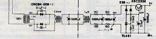
Preregulators like µ7818 ; LM317 or LT1086 introduce a lot of noise into the system that is difficult to get rid off. More important <B><U>Sound </B></U>is better without the preregulators.
For still better ripple reduction I am using a PI-filter in the raw supply. And believe it or not a 2.2mH choke in the ground connection to the center tap of the transformer. This mod by John Curl. I did not believe it but sound was better with this choke.
Without tricks it is difficult to get 15.6 V out of a opamp powered from a 15V single supply needed to drive the base of the pass transistor.-
Harry,HarryHaller said:There goes the PSRR......... The opamps in the regulator need the best supply go can give them for good PSRR. that is the reason for powering the opamp from the supply it is providing the regulation for. Preregulators are also a good idea for best PSRR.
H.H.
My circuit is very similar to the one in the link fig. 26.
http://www.analog.com/library/applicationNotes/AdAudio/AN394.pdf
I completely lost interest in posting my own circuit
Preregulators like µ7818 ; LM317 or LT1086 introduce a lot of noise into the system that is difficult to get rid off. More important <B><U>Sound </B></U>is better without the preregulators.
For still better ripple reduction I am using a PI-filter in the raw supply.
And believe it or not a 2.2mH choke in the ground connection to the center tap of the transformer. This mod by John Curl. I did not believe it but sound was better with this choke.Without tricks it is difficult to get 15.6 V out of a opamp powered from a 15V single supply needed to drive the base of the pass transistor.
-Re: Voltage regs
Your idea is partially realised by Thorsten Loesch who uses a single LM6181 to power a line stage without pass transistor.
http://groups.yahoo.com/group/Thunderstone_technical/files/TL Circuits/FET6181LINE.GIF
Hi Jan,janneman said:I think if we want to make real progress with these regulators, we're looking in the wrong direction. We keep on looking for *good* audio opamps for regulators. What we need is high gain, low noise, high bandwidth, low output impedance and high drive current.
Your idea is partially realised by Thorsten Loesch who uses a single LM6181 to power a line stage without pass transistor.
http://groups.yahoo.com/group/Thunderstone_technical/files/TL Circuits/FET6181LINE.GIF
decided on LT1085
You want 5 volts out at what current and input voltage? I may have an hot rod LT1085 circuit that is pretty simple....... As three terminal regulators go it is one of the best. Make sure you get the LT vesersion and not a second source like the LM1085 from National
H.H.
You want 5 volts out at what current and input voltage? I may have an hot rod LT1085 circuit that is pretty simple....... As three terminal regulators go it is one of the best. Make sure you get the LT vesersion and not a second source like the LM1085 from National
H.H.
Simple Emittor Follower regulator without Feedback
For digital +5V circuit I am using the similar LT1086.
The simple emittor follower I use in my old Tandberg 10XD open reel recorder for +18V supply.
Tandberg originally used a very noisy 18V zener that I replaced with the capacitor bypassed zener emittor follower circuit.
Also I am using the simple emittor follower circuit; without feedback from the output; in the KWAK-CLOCK [low jitter crystal oscillator for CD-players] just as Jocko suggested and in your picture {TL431, NPN transistor}.
I realise that such a circuit has very poor load regulation, if any, but that should not be a very big problem in a clock circuit with a constant current need.
Hi Peter,Peter Daniel said:Does anybody has an experience with a simple regulator following it? I was tempted to try it as well but eventually decided on LT1085.
For digital +5V circuit I am using the similar LT1086.
The simple emittor follower I use in my old Tandberg 10XD open reel recorder for +18V supply.
Tandberg originally used a very noisy 18V zener that I replaced with the capacitor bypassed zener emittor follower circuit.
Also I am using the simple emittor follower circuit; without feedback from the output; in the KWAK-CLOCK [low jitter crystal oscillator for CD-players] just as Jocko suggested and in your picture {TL431, NPN transistor}.
I realise that such a circuit has very poor load regulation, if any, but that should not be a very big problem in a clock circuit with a constant current need.
General Picture about power Supply regulators
Hi Peter,
For me a general picture emerges about the power supply regulators:
For clock circuits a simple emittor follower without any feed back from the output of the regulator is best.
For general digital circuits LT1086 or LT1085 is good. And for line stage preamplifier or MC moving coil phono stage amplifier opamp/follower circuit is best.
My tentative explanation is that the feedback circuit of the regulator "does not like" the clock pulses on the supply.
This is supported by experimental work; not Pspice.
Re: decided on LT1085
The input voltage is around 12-14V and current 250mA.
HarryHaller said:You want 5 volts out at what current and input voltage? I may have an hot rod LT1085 circuit that is pretty simple.......
H.H.
The input voltage is around 12-14V and current 250mA.
LT1085
Some day, and that day may never come, I'll call upon you to do a service for me. But uh,
until that day -- accept this just as a gift .....
First read
http://www.linear-tech.com/pdf/1083fds.pdf
Some day, and that day may never come, I'll call upon you to do a service for me. But uh,
until that day -- accept this just as a gift .....
First read
http://www.linear-tech.com/pdf/1083fds.pdf
Attachments

dangerous to subsequent circuits
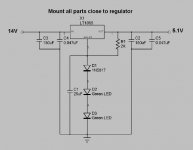
Yes as would the failure of a resistor or zener or even the regulator IC. The LEDS are run at very low current and are actually very rugged, what is your concern? You could put a 5 watt zener selected for about 0.5 volts greater than the output voltage across the output and fuse the inputs before the decoupling cap on the input of the regulator for additional protection if desired. Most logic circuits will take up to 7 volts on the rail without failure.
Yes as would the failure of a resistor or zener or even the regulator IC. The LEDS are run at very low current and are actually very rugged, what is your concern? You could put a 5 watt zener selected for about 0.5 volts greater than the output voltage across the output and fuse the inputs before the decoupling cap on the input of the regulator for additional protection if desired. Most logic circuits will take up to 7 volts on the rail without failure.
what is your concern?
Actually I'm using two regulators. One is 5V for digital, second is 10V for servos. I had to do some changes to original schematic to achieve required values. For 5V I used 2 LEDs and 1K resistor and for 10V I had to use 4 LEDs and 200ohm resistor. So in second case the LEDs are quite bright, but still OK. When I was soldering them in a vise, I pressed too hard and one failed, after checking the circuit I noticed the higher voltage. So that's where my concern is coming from. If for some reasons one of them fails the whole CD-Pro goes down (pre reg. voltage is like 16V or so). That's why I started to think about using maybe resistors, they more rugged. But then my impression is the LEDs probably sound better.
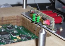
I made my best to keep components close to regulators. They are under Cerafine caps.
Actually I'm using two regulators. One is 5V for digital, second is 10V for servos. I had to do some changes to original schematic to achieve required values. For 5V I used 2 LEDs and 1K resistor and for 10V I had to use 4 LEDs and 200ohm resistor. So in second case the LEDs are quite bright, but still OK. When I was soldering them in a vise, I pressed too hard and one failed, after checking the circuit I noticed the higher voltage. So that's where my concern is coming from. If for some reasons one of them fails the whole CD-Pro goes down (pre reg. voltage is like 16V or so). That's why I started to think about using maybe resistors, they more rugged.
But then my impression is the LEDs probably sound better.I made my best to keep components close to regulators. They are under Cerafine caps.
Attachments
- Status
- This old topic is closed. If you want to reopen this topic, contact a moderator using the "Report Post" button.
- Home
- Amplifiers
- Solid State
- Voltage regulators for line level circuits