Sadly i have no way of getting the source code cus i have no ideea who has it, or rather who wrote it... than all i can hope is that the software interpretation pf the analog imput is linear and an adjustable gain ( witch it's easy to make possible ) will be enough to make it work.
As for the other thing, you are right ofcourse, appologyes for my absurdity, and thanks again for your interest.
As for the other thing, you are right ofcourse, appologyes for my absurdity, and thanks again for your interest.
Since you have the possibility to use floating supplies, a powerful and accurate method of remote sensing/rapatriation is to use current sources, a bit like Palstanthurin showed, but more flexible: the voltage rating is that of the discrete transistor, not the opamp.
In addition, it requires no accurate matching, and ranges can easily be altered/switched with R3/R6.
Here it is shown with small MOSfets for maximum accuracy, but high Hfe Bjt's are also usable with a slightly degraded accuracy.
The opamps can be almost any type, like TLO81 or LM358, but precision opamps are preferable of course.
Attachments
Thanks @Elvee, i see now that i was verry ignorant and i apologise for it, there are enough solutions for it, i've just not searched enough...
So moving the shunt it is clearely not a problem, the issue is the source code witch i cannot get it and without it it seams i cannot make sure the hex file is ok, i'll just have to hope that adjustable amplification will be indeed enough to calibrate it afterwards.
So moving the shunt it is clearely not a problem, the issue is the source code witch i cannot get it and without it it seams i cannot make sure the hex file is ok, i'll just have to hope that adjustable amplification will be indeed enough to calibrate it afterwards.
Greetings.
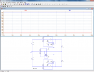
I'm back with an upgrade on the device, after further research and testing i have stopped at this schematic for it:

For the current part i will use the differencial amplifier with a LM358, i will provide a 20Vcc to cover the imputs limmits regarding CMIR, and an noninverter amplifier to get the needed voltage, after testing with what i had i have found that BZX55C5V1 is the best option regarding the protection of the PIC's imput, it has the smallest effect on the voltage below it's breakdown level. The device is set for 0 to 35Vcc and 0 to 6A, it will also indicate the power delivered to the load, my PSU will have a max of about 31Vcc and a limmited current of arround 5A. The speaker is a buzzer witch will go off when reading exactly 6A on the LCD, the same function for the LED, they both will give visual and auditory warning when that level is reached for any given reason, another way of ensurring the safety of the PIC microcontroller.
I had a friend wrote the code for me and debug it, i have wrote it into the PIC and after mounting stuff on a breadboard i have run a test, it seams it's going ok, the voltage indication is precise enough, no important deviation from the indication of a digital multimeter when adjunsting the PSU's level. haven't had the time to make up on the board the current side of the device, i will leave that for the PCB when it's done, i have assured and adjustable 0-5V to the current imput and the indication on the LCD display is going up and down quite good, havin exactly 6A for 5Vcc on the imput, i attach a pic showing it in action:

The buzzer goes off exactly at 6A, le indications are good enough so i think it is ok to call it a success, now comes the pcb witch i designed it few days ago and will be put into practice as soon as possible:

Regards,
Marian.
I'm back with an upgrade on the device, after further research and testing i have stopped at this schematic for it:
For the current part i will use the differencial amplifier with a LM358, i will provide a 20Vcc to cover the imputs limmits regarding CMIR, and an noninverter amplifier to get the needed voltage, after testing with what i had i have found that BZX55C5V1 is the best option regarding the protection of the PIC's imput, it has the smallest effect on the voltage below it's breakdown level. The device is set for 0 to 35Vcc and 0 to 6A, it will also indicate the power delivered to the load, my PSU will have a max of about 31Vcc and a limmited current of arround 5A. The speaker is a buzzer witch will go off when reading exactly 6A on the LCD, the same function for the LED, they both will give visual and auditory warning when that level is reached for any given reason, another way of ensurring the safety of the PIC microcontroller.
I had a friend wrote the code for me and debug it, i have wrote it into the PIC and after mounting stuff on a breadboard i have run a test, it seams it's going ok, the voltage indication is precise enough, no important deviation from the indication of a digital multimeter when adjunsting the PSU's level. haven't had the time to make up on the board the current side of the device, i will leave that for the PCB when it's done, i have assured and adjustable 0-5V to the current imput and the indication on the LCD display is going up and down quite good, havin exactly 6A for 5Vcc on the imput, i attach a pic showing it in action:
The buzzer goes off exactly at 6A, le indications are good enough so i think it is ok to call it a success, now comes the pcb witch i designed it few days ago and will be put into practice as soon as possible:
Regards,
Marian.
Greetings.
I'm back with an upgrade on the device, after further research and testing i have stopped at this schematic for it:
If that is sufficient to meet your objectives, why not but I think it is worth drawing your attention to some points.
-R6 to R9 will require a very accurate matching. For example, with 0.01% tolerance, a 20V variation of the output could "leak" as a 160mA parasitic current variation.
-The offset of the 358 will also cause errors: 5mV will result in a 100mA error; a precision (or offset-trimmable) opamp would be preferable.
-To protect effectively the input of the PIC without losing accuracy, you can use a lower voltage zener, 4.7 or 4.3V and connect P1 downstream of R11
I am well aware of the amplifier's shortcomings regarding resistor matching, that is why i bought loads of 10k resistors all from the same batch, i am pretty sure i will find 4 of them close enough; i am also aware of the offset influence but all i can do is try out more than one 358 and choose the one with the smallest offset as i am quite sure it cannot be the same to all of them... on the other hand i am not looking for precision current rating, differencial amplifier makes that quite hard to obtain, but i do not need that, i am not building an multimeter so i just need to have at least some ideea of the load current at any given time and i am quite sure i will be satisfyed even with that worst case scenario you have described, so i am done testing, i just need to make the time for the board it's self and then again some more testing and adjusting what needs to be adjusted, and that would be it...
PS: All i am worryed about is the case for the PSU witch i do not have it and i doubt verry much i will be able to afford something real nice, maybe i'll try and construct it or modify a PC case or something like that...
PS: All i am worryed about is the case for the PSU witch i do not have it and i doubt verry much i will be able to afford something real nice, maybe i'll try and construct it or modify a PC case or something like that...
Greetings everyone.
I have recently finished the VA-meter i was working on, it has been mounted on an adjustable Lab Power Supply built by me, the digital meter uses PIC16F876A and a 2x24 LCD, it measures Voltage on the load, Current taken by the load, power delivered to the load and the main heatsink temperature, this is how i wanted to be, this is the complete schematic:

Temperature circuit and digital part is powered from a small sepparate transformer, as for the current monitoring part, it is powered from an auxiliary winding on the main power transformer, this is so when the overtemperature threshold is reached the digital part is unaffected by main power transformer shut down. This is the source code written by me ( the code it's self it's written for romanian language, but i have translated now the comments in english ):
This is a short clip with digital meter in final breadboard testing:
Test practic Afisaj digital multiplu - YouTube
I have recently finished the VA-meter i was working on, it has been mounted on an adjustable Lab Power Supply built by me, the digital meter uses PIC16F876A and a 2x24 LCD, it measures Voltage on the load, Current taken by the load, power delivered to the load and the main heatsink temperature, this is how i wanted to be, this is the complete schematic:
Temperature circuit and digital part is powered from a small sepparate transformer, as for the current monitoring part, it is powered from an auxiliary winding on the main power transformer, this is so when the overtemperature threshold is reached the digital part is unaffected by main power transformer shut down. This is the source code written by me ( the code it's self it's written for romanian language, but i have translated now the comments in english ):
Code:
/* Description:
 * Digital multimeter for adjustable lab Power Supply
 * Display Voltage 0-35Vdc, Current 0-6Adc, Power to the load
 * and main heatsink temperature 0-100*C
 * Features:
 * Visual and audible warning for reaching voltage
 * and/or current threshold
 * Main power transformer shut down when main heatsink reaches 90*C
 * Config:
 * Microcontroller PIC16F876A
 * Oscilator XT 4.000 Mhz
 * LCD Alfanumeric 2x24
 * Author: MarianB.
 * Iul-2013
*/


//LCD Connections
sbit LCD_RS at RB7_bit;
sbit LCD_EN at RB6_bit;
sbit LCD_D4 at RB5_bit;
sbit LCD_D5 at RB4_bit;
sbit LCD_D6 at RB3_bit;
sbit LCD_D7 at RB2_bit;

sbit LCD_RS_Direction at TRISB7_bit;
sbit LCD_EN_Direction at TRISB6_bit;
sbit LCD_D4_Direction at TRISB5_bit;
sbit LCD_D5_Direction at TRISB4_bit;
sbit LCD_D6_Direction at TRISB3_bit;
sbit LCD_D7_Direction at TRISB2_bit;

//Declare variables
unsigned char ch, ADCx;
unsigned int Tensiune, Curent, Temp, ProtU, ProtI, ProtT;
unsigned long V, A, Pw, T;

//Main function
void main() {
     INTCON = 0;                             // Interrupt off
     TRISA = 0x07;                           // RA0, RA1 si RA2 set as In ports
     TRISC = 0;                              // Portul C set as Out port
     PORTC = 0;                              // Reset port C

     Lcd_Init();                             // Initialize LCD
     Lcd_Cmd(_LCD_CURSOR_OFF);               // Deactivate cursor
     Lcd_Cmd(_LCD_CLEAR);                    // Clear screen
     Delay_ms(1000);                         // Delay 1 sec
     Lcd_Out(1,1,"SursaSimetricaLaborator"); // First message, line 1, column 1
     Lcd_Out(2,1,"Afisaj Digital Multiplu"); // First message, line 2, column 1
     Delay_ms(3000);
     Lcd_Cmd(_LCD_CLEAR);                    // Clear screen
     Lcd_Out(1,4,"0-35V; 0-6A; 0-100C");     // Second message, line 1, column 4
     Lcd_Out(2,8,"<By Marian>");             // Second message, line 2, column 8
     Delay_ms(3000);
     Lcd_Cmd(_LCD_CLEAR);
     Lcd_Out(1,1,"U:");                      // Display "U", line 1, column 1
     Lcd_Out(1,10,"T:");                     // Display "T", line 1, column 10
     Lcd_Out(1,19,"C");                      // Display "C", line 1, column 19
     Lcd_Out(2,1,"I:");                      // Display "I", line 2, column 1
     Lcd_Out(2,10,"P:");                     // Display "P", line 2, column 10

      while (1) {
            //ADC Reading
            Tensiune = 0;
            Curent = 0;
            Temp = 0;
            for (ADCx=0; ADCx<10; ADCx++) {
            Tensiune += ADC_Read(2);         // Voltage reading
            Curent += ADC_Read(1);           // Current reading
            Temp += ADC_Read(0);             // Temperature reading
            Delay_ms(10);
            }

            //Voltage
            Tensiune = Tensiune/ADCx;        // Set voltage vallue
            V = (long)Tensiune*3500;         // Convert result in milivolts
            V = V/1023;                      // 0...1023 => 0...3500mV
            ch = V/1000;                     // Extract 10.00
            Lcd_Chr(1,3,48+ch);              // Display result in format ASCII
            ch = (V/100) % 10;               // Extract 01.00
            Lcd_Chr_CP(48+ch);               // ADisplay result in format ASCII
            Lcd_Chr_CP('.');                 // Display '.'
            ch = (V/10) % 10;                // Extract 00.10
            Lcd_Chr_CP(48+ch);
            ch = V % 10;                     // Extract 00.01
            Lcd_Chr_CP(48+ch);
            LCD_Chr_CP('V');                 // Display 'V'
            Delay_ms(10);

            //Current
            Curent = Curent/ADCx;            // Set current vallue
            A = (long)Curent*600;            // Convert result in milivolts
            A = A/1023;                      // 0..1023 => 0-600mV
            ch = A/1000;                     // Extract 10.00
            Lcd_Chr(2,3,48+ch);              // Display result in format ASCII
            ch = (A/100) % 10;               // Extract 01.00
            Lcd_Chr_CP(48+ch);
            Lcd_Chr_CP('.');
            ch = (A/10) %10;                 // Extract 00.10
            Lcd_Chr_CP(48+ch);
            ch = A % 10;                     // Extract 00.01
            Lcd_Chr_CP(48+ch);
            Lcd_Chr_CP('A');                 // Display 'A'
            Delay_ms(10);

            //Temperature
            Temp = Temp/ADCx;                // Set temperature vallue
            T = (long)Temp*1000;             // Convert result in milivolts
            T = T/1023;                      // 0...1023 => 0...1000mV
            ch = T/1000;                     // Extract 100.00
            Lcd_Chr(1,12,48+ch);             // Display result in format ASCII
            ch = (T/100) % 10;               // Extract 010.00
            Lcd_Chr_CP(48+ch);
            ch = (T/10) % 10;                // Extract 001.00
            Lcd_Chr_CP(48+ch);
            Lcd_Chr_CP('.');
            ch = (T/1) % 10;                 // Extract 000.10
            Lcd_Chr_CP(48+ch);
            ch = T % 10;                     // Extract 000.01
            Lcd_Chr_CP(48+ch);
            Lcd_Chr_CP(223);                 // Display char "degree"
            Delay_ms(10);

            //Power
            Pw = V*A/1000;                   // Set power vallue
            ch = Pw/1000;                    // Extract 100.00
            Lcd_Chr(2,12,48+ch);
            ch = (Pw/100) % 10;              // Extract 010.00
            Lcd_Chr_CP(48+ch);
            ch = (Pw/10) %10;                // Extract 001.00
            Lcd_Chr_CP(48+ch);
            Lcd_Chr_CP('.');
            ch = (Pw/1) % 10;                // Extract 000.10
            Lcd_Chr_CP(48+ch);
            ch = Pw % 10;                    // Extract 000.01
            Lcd_Chr_CP(48+ch);
            Lcd_Chr_CP('W');                 // Display "W"
            Delay_ms(10);

            //Protections
            ProtU = ADC_Read(2);             // ADC reading for overvoltage protection
            if (ProtU > 995) {
            PORTC.F4 = 1;                    // Power up LED if voltage is 34V
            Sound_Init(&PORTC, 3);           // Initialize buzzer, and activate sound warning
            Sound_Play(500, 1000);           // 500Hz, 1 second if voltage is 34V
            }
            else {
            PORTC.F4 = 0;                    // Reset RC4
            }

            ProtI = ADC_Read(1);             // ADC reading for overcurrent protection
            if (ProtI > 1000) {
            PORTC.F5 = 1;                    // Power up LED if current is 5,8A
            Sound_Init(&PORTC, 3);           // Initialize buzzer, and activate sound warning
            Sound_Play(600, 500);            // 600Hz, 500mS if current is 5,8A
            }
            else {
            PORTC.F5 = 0;                    // Reset RC5
            }

            ProtT = ADC_Read(0);             // ADC reading for overtemperature protection
            if (ProtT > 920) {
            PORTC.F2 = 1;                    // Power up relay if temperature is 90*C
            Lcd_Cmd(_LCD_CLEAR);             // Clear screen
            Lcd_Out(1,8,"PROTECTIE!");       // Display warning message on LCD,
            Lcd_Out(2,5,"SUPRATEMPERATURA"); // "Overtemperature Protection"
                do {
                }                            // Endless loop
               while (1);
            }
            else {
            PORTC.F2 = 0;
            }

      }
}
This is a short clip with digital meter in final breadboard testing:
Test practic Afisaj digital multiplu - YouTube
- Status
- This old topic is closed. If you want to reopen this topic, contact a moderator using the "Report Post" button.
- Home
- Amplifiers
- Power Supplies
- Volt-Ammeter