Hi all,
I am rebuilding two 15" subs, I have already rewound both voice coils; one SVC and the other a Dual VC, I am nearly ready to connect them to the terminals. This may sound a bit fundamental as I am new to this but which end of the voice coil wire should be your positive (+), and which is your negative (-) or does it matter? I assume the first layer wound would be the negative and outer the positive, because its closest to the magnet, and also the DVC is wired (1st coil 1st layer, 2nd coil 1st layer, 1st coil 2nd layer and 2nd coil 2nd layer) wound in interleave. Please verify this if possible!
I am rebuilding two 15" subs, I have already rewound both voice coils; one SVC and the other a Dual VC, I am nearly ready to connect them to the terminals. This may sound a bit fundamental as I am new to this but which end of the voice coil wire should be your positive (+), and which is your negative (-) or does it matter? I assume the first layer wound would be the negative and outer the positive, because its closest to the magnet, and also the DVC is wired (1st coil 1st layer, 2nd coil 1st layer, 1st coil 2nd layer and 2nd coil 2nd layer) wound in interleave. Please verify this if possible!
Impossible to answer without knowing the direction of winding.
Drop the coil in the gap, apply some DC current (1.5 volt battery should do) and see which way it goes.
Normal convention is positive voltage to the + terminal makes the coil go away from the magnet structure.
Drop the coil in the gap, apply some DC current (1.5 volt battery should do) and see which way it goes.
Normal convention is positive voltage to the + terminal makes the coil go away from the magnet structure.
Attachments
Thank you for the input! To answer: the direction of the winding, I wound it exactly as it was originally factory wound; first coil in one direction and second coil in opposite direction, it seems to make sense to me, but it was very difficult to wind them inside one another as I only used a drill for spooling with a fabricated steel pipe as a spigot; after winding the first layer, I put the wire bobbin inside the pipe while I started the second coil first layer and so on, I think next time I will just completely wind the coil 1 and then wind coil 2 both layers on top of 1. My guess is that if I wind them interleaved as I first said, the coils amplify one another much stronger. Well maybe?
Also I am happy to give it some current, but will a 9 volt battery cause any harm if fouled?
Also I am happy to give it some current, but will a 9 volt battery cause any harm if fouled?
weltersys
Impossible to answer without knowing the direction of winding.
Drop the coil in the gap, apply some DC current (1.5 volt battery should do) and see which way it goes.
Normal convention is positive voltage to the + terminal makes the coil go away from the magnet structure.
You only have to give it a burst, a fraction of a second....Also I am happy to give it some current, but will a 9 volt battery cause any harm if fouled?
So no, you won't hurt the coil.
Tried to bump both coils and also tried checking resistance with multimeter, No Response! I haven't a clue what is wrong, even if there's a discrepancy in the winding, I never severed any wiring so there should be a reaction! Am I wrong?
Quote:
weltersys
Impossible to answer without knowing the direction of winding.
Drop the coil in the gap, apply some DC current (1.5 volt battery should do) and see which way it goes.
Normal convention is positive voltage to the + terminal makes the coil go away from the magnet structure.
Quote:
weltersys
Impossible to answer without knowing the direction of winding.
Drop the coil in the gap, apply some DC current (1.5 volt battery should do) and see which way it goes.
Normal convention is positive voltage to the + terminal makes the coil go away from the magnet structure.
you should be able to measure a resistance.
If not then the first winding is shorted to the last winding.
If you have a finite resistance, but get no force due to coil current, then maybe
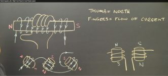
Both coils are wound in the same direction. But the helix is in the opposite direction.
If not then the first winding is shorted to the last winding.
If you have a finite resistance, but get no force due to coil current, then maybe
this is the problem.first coil in one direction and second coil in opposite direction,
Both coils are wound in the same direction. But the helix is in the opposite direction.
Dear 1977
This will also depend on the direction of magnetizing of the motor structure carried out by the manufacturer of your driver . Once the permanent magnetizing direction is known the B of your coil and resulting direction of coil magnetizing can be considered .
In this case the best is to carry out the battery test as suggested by everyone earlier . For your reference any regular polyester insulated magnet wire below 36 swg will not burn with a 9 v battery .
The permanent magnetizing direction and the subsequent connecting of inner or outer layer to +ve or -ve terminal will not have any effect on the wave produced , as long as the above polarity test is followed .
For a successful coil renewal the following should be looked into :-
1) Cleaning of the magnetic gap , should be free from any particles
2) Matching of the length of winding & ohms , basically inductance of the coil overall
3) Type of insulation of the wire used
4) Type of inter-layer bonding (fro eg self bonding wire or regular magnet wire)
5) placing of voice coil , sometimes it is not essential the coil will be at the exact center of the magnetic gap , the position should be noted upon removal of the dustcap
6) The bobbin ID & outer layer od , should be as close to original as possible
7) Positioning the voice coil between the top plate & pole piece
8) removing the insulation of the vc wire & soldering quality
9) overall dexterity & workmanship / quality of adhesives
Suranjan
Suranjan:
Referring to sequence 8 above, I was previously told at the shop where I bought the coil wire that of its insulated nature and he also added that it would have to be somehow stripped or spliced before winding takes place, now I took a pretty detailed look at the wire and just cannot see where I can physically strip this wire, looks like ordinary solid but flexy coil wire. I do believe there is some sort of protective coating on the wire so that they don't actually touch as wound, I guess that might be why I'm not getting a response when probing for a reaction, il try to scale some of the enamel back with a razor blade near the tips of the wire and resume bump test! I must thank all of you for your attention!
This will also depend on the direction of magnetizing of the motor structure carried out by the manufacturer of your driver . Once the permanent magnetizing direction is known the B of your coil and resulting direction of coil magnetizing can be considered .
In this case the best is to carry out the battery test as suggested by everyone earlier . For your reference any regular polyester insulated magnet wire below 36 swg will not burn with a 9 v battery .
The permanent magnetizing direction and the subsequent connecting of inner or outer layer to +ve or -ve terminal will not have any effect on the wave produced , as long as the above polarity test is followed .
For a successful coil renewal the following should be looked into :-
1) Cleaning of the magnetic gap , should be free from any particles
2) Matching of the length of winding & ohms , basically inductance of the coil overall
3) Type of insulation of the wire used
4) Type of inter-layer bonding (fro eg self bonding wire or regular magnet wire)
5) placing of voice coil , sometimes it is not essential the coil will be at the exact center of the magnetic gap , the position should be noted upon removal of the dustcap
6) The bobbin ID & outer layer od , should be as close to original as possible
7) Positioning the voice coil between the top plate & pole piece
8) removing the insulation of the vc wire & soldering quality
9) overall dexterity & workmanship / quality of adhesives
- Status
- This old topic is closed. If you want to reopen this topic, contact a moderator using the "Report Post" button.
- Home
- Loudspeakers
- Subwoofers
- Voice Coil rewind & refitting