You won't run across higher DC with lower AC impedance. The DC voice coil resistance is in series with everything else in the equivalent circuit model of a driver, so the impedance will always be higher than the DC minimum. Around resonance the motional impedance raises the impedance way above the DCR. At high frequencies the inductance dominates and raises impedance above the DCR. At middle frequencies you may get close to DCR, but driver efficiency will still reflect some acoustic resistance back in, raising the Ac impedance.
This isn't really a figure of merit anyhow. You design a speaker to have an impedance that the amplifier is comfortable with. Having a higher or lower impedance means nothing to performance potential, only to sensitivity for a constant voltage input.
Regards,
David
This isn't really a figure of merit anyhow. You design a speaker to have an impedance that the amplifier is comfortable with. Having a higher or lower impedance means nothing to performance potential, only to sensitivity for a constant voltage input.
Regards,
David
I'm looking at different alloys to reduce heat generation in voice coils. They might have higher DC resistivity than Copper to begin with, but a lower temperature coefficient of resistivity.
This website - GlassWolf's Pages - says "The voice coil DC resistance has the biggest impact on speaker impedance. DCR dominates the resistance of a driver at nearly every frequency. Next is inductance on the electrical side. Stray capacitance is miniscule compared to the others, but still there."
Thoughts?
You won't run across higher DC with lower AC impedance. The DC voice coil resistance is in series with everything else in the equivalent circuit model of a driver, so the impedance will always be higher than the DC minimum. Around resonance the motional impedance raises the impedance way above the DCR. At high frequencies the inductance dominates and raises impedance above the DCR. At middle frequencies you may get close to DCR, but driver efficiency will still reflect some acoustic resistance back in, raising the Ac impedance.
This isn't really a figure of merit anyhow. You design a speaker to have an impedance that the amplifier is comfortable with. Having a higher or lower impedance means nothing to performance potential, only to sensitivity for a constant voltage input.
Regards,
David
I do not think this statement could be more false. Re is probably one of the 3 most important of all of the T/S parameters along with Mms and Bl. Your Bl is directly a function of Re as were you to keep the magnet structure the same, the only way to increase it is to increase l. That involves carefully balancing winding length, layers, and gauge all of which change the Re of the driver, which also affects the Mms due to more or less wire moving during the stroke, and also affects your eta. Re is hugely important, far more so than Z. In fact, a "4" ohm driver notion is meaningless as the Re could be 4, 3.6, 3.4, 3.2, or 2.7 ohms, and then depending on the above factors and the driver's other parameters you could easily end up with something that is nominally 5 or nominally 3. When doing non-linear analysis, there are only 3 parameters that matter as starting points: Re, Bl, and Mms.AC impedance is the specification. The DC resistance has little meaning.
Last edited:
This is because as a driver moves beyond its linear region, coil heating raises driver impedance. The small signal parameters no longer apply, so a coil which rises dramatically from Re is one that needs serious heat relief measures. You can control inductance of the driver in many ways. You can only change the DCR (temporarily mind you) by heating or cooling the coil. If you have a "4 ohm" driver with a copper cap shorting ring in it, (let's say an Le of 0.05mH), then the DCR is going to determine that driver's impedance above and below resonance more than any other factor. You can have a 2.7ohm Re with ultra high inductance and therefore get away with a 4 ohm rating. That 2.7ohm DCR but 4 ohm nominal rating will let you know that without even looking at anything else (assuming the manufacturer didn't lie).I'm looking at different alloys to reduce heat generation in voice coils. They might have higher DC resistivity than Copper to begin with, but a lower temperature coefficient of resistivity.
This website - GlassWolf's Pages - says "The voice coil DC resistance has the biggest impact on speaker impedance. DCR dominates the resistance of a driver at nearly every frequency. Next is inductance on the electrical side. Stray capacitance is miniscule compared to the others, but still there."
Thoughts?
Hi,
Inductance has nothing much to do with it.
rgds, sreten.
The inductance means the impedance goes up with audio frequency.
So it will have an effect.
I have a Fane Sovereign 12-250TC which has 1.56mH inductance.
At 5KHz this gives 49 ohms which is much greater than Re.
Last edited:
Things would be easy if moving-coil drivers were just simple flat resistance, but for the most part, they are not.
Voicecoil inductance Le and DC resistance Re are interrelated. Where it gets interesting is when you add copper damping rings to the pole piece. This has the effect of reducing voicecoil inductance.
Which then extends frequency response. Because inductance limits frequency response because it creates a LR filter.
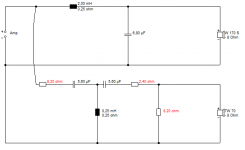
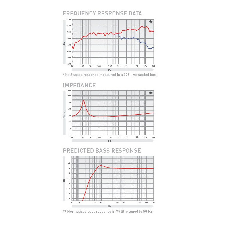
In practise, voicecoil inductance is not much of a problem. It's sort of built into the usual filter. What looks like a second order bass in the first image, is actually a third order with the phantom 1.2mH inductance of the Visaton W170S here.
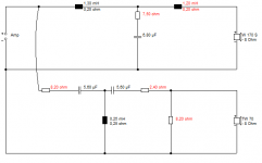
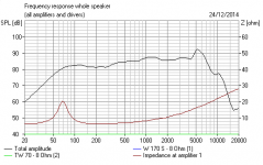
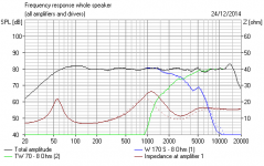
I then show a second circuit which has almost identical frequency response with that same W170S driver. That's how it works. We can therefore add resistance and take out inductance in the filter to correct the rising inductance of the driver. I include a third image of the unfiltered bass driver in the 12L box to show raw impedance and response. The fourth image shows how equivalent the two circuits are.
The big idea, is that if the driver has inductance, which gets worse with frequency, you can then remove it from the filter, if you follow? If it has no inductance, you might want to add some. For all that, I suspect the low inductance driver will sound better ultimately. But will need a more complex filter.
Don't know if I explained that well. But there's more than one way to skin a cat.
Voicecoil inductance Le and DC resistance Re are interrelated. Where it gets interesting is when you add copper damping rings to the pole piece. This has the effect of reducing voicecoil inductance.
Which then extends frequency response. Because inductance limits frequency response because it creates a LR filter.
In practise, voicecoil inductance is not much of a problem. It's sort of built into the usual filter. What looks like a second order bass in the first image, is actually a third order with the phantom 1.2mH inductance of the Visaton W170S here.
I then show a second circuit which has almost identical frequency response with that same W170S driver. That's how it works. We can therefore add resistance and take out inductance in the filter to correct the rising inductance of the driver. I include a third image of the unfiltered bass driver in the 12L box to show raw impedance and response. The fourth image shows how equivalent the two circuits are.
The big idea, is that if the driver has inductance, which gets worse with frequency, you can then remove it from the filter, if you follow? If it has no inductance, you might want to add some. For all that, I suspect the low inductance driver will sound better ultimately. But will need a more complex filter.
Don't know if I explained that well. But there's more than one way to skin a cat.
Attachments
Precisely. Re is the single most important of the electrical T/S parameters.Hi,
Nominal Re defines the drivers impedance.
Inductance has nothing much to do with it.
Typically Re for 4 ohm may be 2.7 to 3.1 R,
and for 8 ohm 5.6 to 6.2 R, for most cases.
rgds, sreten.
Precisely. Re is the single most important of the electrical T/S parameters.
I'm not sure why any T/S parameter is more important than the next. You would need them all to describe woofer performance. In the end (Bl)squared over Re is the key factor for motor strength and electrodynamic damping. With it the l squared over Re ratio lets you have equivalent performance for any Re as long as you maintain the volume of copper in the gap constant (i.e., you could start with a cylinder of copper and slice it into any number of finer and finer turns and the (Bl)sqrd/Re factor would remain constant.
Voltage sensitivity may change but power efficiency and curve shape would not.
David
No Silver Bullet Here.
Most the parameters you will be dealing with in speaker design do not have monotonic values. If you boil down your speaker design into a TSP plug and chug routine, you will never get beyond the margins of achieving just an acceptable design. System as well as component performance needs to be evaluated over the domains of both frequency and time. Design of such systems, is always an iterative process, that requires such evaluations to be made, if some degree of excellence in system performance is to be achieved.
Avoid designs that are over sensitive to driver parameter variation. Such variation will not only occur between driver production lots of the same model, but also over the passage of time as well. Do a sensitivity analysis of your design, particularly if you are going to take it commercial.
Regards,
WHG
I'm looking at different alloys to reduce heat generation in voice coils.
Have you estimated the real heat generated in your typical listening conditions ?
Simple Question ...
... Simple Answer: Impedance is more important.
[Re], the DC Resistance of the voice coil winding, is the floor limit of Impedance and it is monotonic.
Impedance is not. It is frequency dependant; so, it does not have a single value (measure). instead, it is represented by a set of values that may be taken at arbitrary frequency intervals.
Thus, if you are designing a loudspeaker it is far more important.
TSP's, and particularly [Qts], are derived from it in combination with other traditional measures.
I still prefer Leach's [1] boil-down of Thiel/Small's treatment of loudspeaker parameters. For those that have these kinds of questions, his book [2] will be a worth-while read.
Regards,
WHG
References
[1] W. Marshall Leach, Jr.
[2] An Introduction to Electroacoustics and Audio Amplifier Design
All other things being equal -
What's more important, a voice coil with a lower DC resistance, or a voice coil with comprable (though higher DC resistance) but lower overall AC impedance?
... Simple Answer: Impedance is more important.
[Re], the DC Resistance of the voice coil winding, is the floor limit of Impedance and it is monotonic.
Impedance is not. It is frequency dependant; so, it does not have a single value (measure). instead, it is represented by a set of values that may be taken at arbitrary frequency intervals.
Thus, if you are designing a loudspeaker it is far more important.
TSP's, and particularly [Qts], are derived from it in combination with other traditional measures.
I still prefer Leach's [1] boil-down of Thiel/Small's treatment of loudspeaker parameters. For those that have these kinds of questions, his book [2] will be a worth-while read.
Regards,
WHG
References
[1] W. Marshall Leach, Jr.
[2] An Introduction to Electroacoustics and Audio Amplifier Design
I feel that there is a large amount of 'tail wagging the dog' going on here.
The OP's question is best left unanswered. In an absence of a defined context of use, all numbers are meaningless.
(P.S: Neither DCR nor Impedance numbers are a rational way of picking the favorite at the races tommorrow )
The OP's question is best left unanswered. In an absence of a defined context of use, all numbers are meaningless.
(P.S: Neither DCR nor Impedance numbers are a rational way of picking the favorite at the races tommorrow
)More
For voice coils, the specific resistance vs. density of the conductor being used is at issue. See the attached PDF file for Baranik’s treatment of this.
Increase driver efficiency (typically low) to reduce heat generation.
I'm looking at different alloys to reduce heat generation in voice coils. They might have higher DC resistivity than Copper to begin with, but a lower temperature coefficient of resistivity.
This website - GlassWolf's Pages - says "The voice coil DC resistance has the biggest impact on speaker impedance. DCR dominates the resistance of a driver at nearly every frequency. Next is inductance on the electrical side. Stray capacitance is miniscule compared to the others, but still there."
Thoughts?
For voice coils, the specific resistance vs. density of the conductor being used is at issue. See the attached PDF file for Baranik’s treatment of this.
Increase driver efficiency (typically low) to reduce heat generation.
Attachments
I feel that there is a large amount of 'tail wagging the dog' going on here.
The OP's question is best left unanswered. In an absence of a defined context of use, all numbers are meaningless.
(P.S: Neither DCR nor Impedance numbers are a rational way of picking the favorite at the races tommorrow
The context is obvious and dog wagging is not at issue. Anyway, at the moment, I am a Santa in wait mode and have nothing better to do untill other family members arise from slumber. ;-) WHG
Last edited:
The inductance means the impedance goes up with audio frequency.
So it will have an effect.
I have a Fane Sovereign 12-250TC which has 1.56mH inductance.
At 5KHz this gives 49 ohms which is much greater than Re.
Hi,
So what ? nominal driver impedance will still be set by Re.
rgds, sreten.
The Fane Sovereign 12-250TC is an 8 ohm driver with
an usually high Re of 7.2R. Your wrong about impedance :
Its clearly not 49 ohms at 5KHz, apparently.
However I find this more realistic :
http://www.parts-express.com/pedocs/specs/290-409-eminence-beta-12lta-specifications-44608.pdf
But its still an 8 ohm driver, albeit say 27 ohms @ 5KHz.
Last edited:
- Status
- This old topic is closed. If you want to reopen this topic, contact a moderator using the "Report Post" button.
- Home
- Loudspeakers
- Multi-Way
- Voice Coil (Resistance v. Impedance)