philbyx said:Hello
I'm working too on a valves I/U. But I want 0v on input, to avoid stressing my dac wich is based on ad1865.
This is just ideas on paper for the moment...
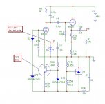
V1=160V
V2=8V
I : 6ma in first tube, 7ma in CF
Tl431 for negative voltage regulation and as ccs reference.
The 15k resistor on the anode of the first tube gives 15V for 1ma full scale on the ad1865.
The simulation works.
hi,Philippe
15V!....stronger!!!

the Q1 is not set to CCS.if Q1 is set to CCS,the circuit can work in a better way.
X.G.
X.G. said:
hi,Philippe
the Q1 is not set to CCS.if Q1 is set to CCS,the circuit can work in a better way.
X.G.
Q1 has a regulated 2.5 Volts (the TL431 reference) on its base
With the 300 ohms on the emitter, we have :
300 x I = 2.5-Vbe
I= (2.1-Vbe)/300 = 1.8/300 = 6ma
I think that this is a CCS.
If 15V is stronger, you can decrease the value of the anode resistor.
Philippe
X.G. said:the Q1 seems to a CCS,but not a enogh good CCS .....the Q1 more like a volt regulator
sorry for my poor English,I can not explain more clear.
X.G.
Hi
Your English is OK, at least I understand your point
Indeed, this configuration with the 431 is a little "strange"
If the base is kept at constant voltage, the emitter will also be at constant voltage, then the emitter current is constant too (so current source)
I would hower suggest to use the 431 a little different:
Add a few 100 ohm series resistor in the anode, the ref input connected to the anode too. Then you have a rigid 2.5V voltage available across the anode-cathode.
succes
X.G. said:
for the CCS of BJT,the circuit should be set the Ib of BJT to constant....but on here,the stability of Ib is not so good,because of the less control of TL431 here than the standard application.
regards
X.G.
Thanks XG and Guido
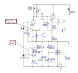
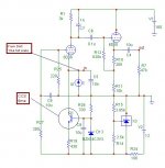
Here is a modified circuit :
The purpose of the tl431 is to give a solid negative voltage referenced to the ground, to drive the grid and to insure 0v on the cathode.
I can adjust this 0v with R15. The 160 V needs tu be very well filtered (bad rejection of the power supply here).
I had connected the base of the ccs to the ref of the TL431 for the zener cost, but I agree with you : this reference is not very good.
Then here is a modified circuit, with also a 3k on the anode of the first tube : 3v peak for 1 ma, then 2.1 volts RMS on the output.
The Cathode follower is no more in direct link, it is because my simulation soft cannot converge if I do it.
Philippe
Attachments
Attachments
X.G. said:I think.... you don't use the D7 and D12 will be better,they just raise the noise.what thay do is supplied by the TL431.
PS:you can add a cap for decoupling the D13 to reduce the noise.
IMO,your circuit is very good now.
good luck.
X.G.
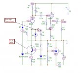
You are right for the cap on D13, my schematic is for the principle, and requires some refinements.
I can't have and adjust the grid voltage directly with the tl431. The Tl431 cannot feed under 2.5 Volts, I need around 2 volts on the grid,then I regulate a greater voltage, and lower it.
I thought about diodes, because it is simple. But as we are regulated, perhaps only resistive bridge like this (R25/R27 and C8 for noise)...
Philippe
Attachments
you need around 2 volts on the grid...why?philbyx said:
I can't have and adjust the grid voltage directly with the tl431. The Tl431 cannot feed under 2.5 Volts, I need around 2 volts on the grid...
Philippe
if you don't use the D7 and D12,the volt between the grid of tube and -V is regulated because of the TL431,and the cathode volt is self-adjusted.if you use the D7 and D12,the results above is the same,but the volt between the grid of tube and -V is regulated because of the D7 and D12.Both of them can work of couse.
EDIT:....but the volt between the grid of tube and -V is regulated because of the D7 and D12
X.G. said:
you need around 2 volts on the grid...why?
To insure 0v on the cathode, wich is the dac input.
Philippe
If the DAC is a true current output, 1,3V couldn't harm.
Coming back to the simple idea, just a 6C45 with cathode resistor, and therefore 1.3 to 2V at the output of the TDA1541A, I consulted again the datasheet of the DAC.
Concerning the output (4mA), they add the following note:
"To ensure no performance losses, permitted output voltage compliance is +-25mV maximum."
Does this refer to the resulting output swing or possibly to bias like above?
Franz
Bernhard said:Can tubes be simulated with microcap ???
everything that can be modelled by math can be simulated ......
cheers
Franz G said:
Coming back to the simple idea, just a 6C45 with cathode resistor, and therefore 1.3 to 2V at the output of the TDA1541A, I consulted again the datasheet of the DAC.
Concerning the output (4mA), they add the following note:
"To ensure no performance losses, permitted output voltage compliance is +-25mV maximum."
Does this refer to the resulting output swing or possibly to bias like above?
Franz
I suspect the swing. This would require an input impedance of 12 ohm or lower.
I just realized: Nuuk published a similar valve output, including LPF filter:
http://myweb.tiscali.co.uk/nuukspot/decdun/cd723vosdiagrams.html
Franz
http://myweb.tiscali.co.uk/nuukspot/decdun/cd723vosdiagrams.html
Franz
Attachments
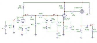
TL´s circuit
Moin Franz,
well, it´s TL´s circuit, for Philips CD 713/723 with TDA1545 - modified for 2mA full scale current - 2 resistors changed, see:
http://www.ptsoundlab.com/sources/lectcd/philips723/phil723.htm
Carsten
Moin Franz,
well, it´s TL´s circuit, for Philips CD 713/723 with TDA1545 - modified for 2mA full scale current - 2 resistors changed, see:
http://www.ptsoundlab.com/sources/lectcd/philips723/phil723.htm
Carsten
- Status
- This old topic is closed. If you want to reopen this topic, contact a moderator using the "Report Post" button.
- Home
- Source & Line
- Digital Source
- vintage tube I/V from the year 1960