Hi,
Well TBH with all this talk of TL's and heavy metal IMHO its
all at crossed purposes given a subwoofer will be involved.
Small drivers are small drivers and do not do SPL very well.
An expanding TQWT (mass loaded or not ?) as a form of
"horn loading" according to some, will maximise output
levels but with the inevitable ripple that comes with it.
") /sreten.
/sreten.
FWIW a electrical impedance matching circuit is bi-directional.
That is the direction of the power flow does not matter.
If you regard it as "tapered" for power flow in one direction,
then in the opposite direction it must be considered "expanding".
Well TBH with all this talk of TL's and heavy metal IMHO its
all at crossed purposes given a subwoofer will be involved.
Small drivers are small drivers and do not do SPL very well.
An expanding TQWT (mass loaded or not ?) as a form of
"horn loading" according to some, will maximise output
levels but with the inevitable ripple that comes with it.
/sreten.FWIW a electrical impedance matching circuit is bi-directional.
That is the direction of the power flow does not matter.
If you regard it as "tapered" for power flow in one direction,
then in the opposite direction it must be considered "expanding".
Hi guys,
After a long time, i finally received my kits. Been doing a bit of research and experimenting with a few designs. Finally came up with this design.
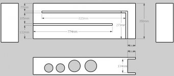
Line length is about 2.8 m, makes it a 30Hz tuning. The internal width of the cabinet is 13.4cm. I know this is much lower than the driver Fs, and the total cabinet volume is about 40L, double the combined VAS of the two drivers which is about 20L. Before i go beyond the point of no return, thought it would be wise to check in with the experienced diyers here.
Any comments / feedback would be much appreciated!
PS: The tweeters have been placed lower in accordance with the golden ratios, to minimize edge diffraction. That results in the rather low positions of the two woofers. How would that affect the sound?
After a long time, i finally received my kits. Been doing a bit of research and experimenting with a few designs. Finally came up with this design.
Line length is about 2.8 m, makes it a 30Hz tuning. The internal width of the cabinet is 13.4cm. I know this is much lower than the driver Fs, and the total cabinet volume is about 40L, double the combined VAS of the two drivers which is about 20L. Before i go beyond the point of no return, thought it would be wise to check in with the experienced diyers here.
Any comments / feedback would be much appreciated!
PS: The tweeters have been placed lower in accordance with the golden ratios, to minimize edge diffraction. That results in the rather low positions of the two woofers. How would that affect the sound?
Attachments
rhapsodee said:I know this is much lower than the driver Fs
Not a good idea. Less bass. less driver damping.
dave
rhapsodee said:Shoud the total volume of the transmission line equal the VAS which is 20l for 2 woofers?
It is not as simple as that. Download Martin Kings tables (linked earlier in the thread) and input your drivers parameters and see what it spits out. (there is a 2nd article that indicates how to change parameters to accomodate 2 drivers)
To my mind a taper in the line adds alot (smaller, better terminus low pass function, better cabinet bracing, if folded)
dave
Recession Buster kit Transmission Line Cab.
First, I wish to thank GM( and Dave of P10 too) for his apparently untiring devotion to educating us clueless newbs'.
Second, I would like to impose on you for a couple of answers again.
Enclosed is a 2D of a Sketchup I've done from the dimensions you gave earlier in this thread.
Specifically does the work I've done reflect what your vision would be, given a 7" cabinet width and dimensions you posted?
How much ( if indeed any ) "fudge" factor can I include when I actually build these? Eg.: would varying the vent +/- 10Pct. cause horrible problems? Following on: Would a similar or smaller variance in Z driver represent catastrophic results? Or, as you said stuff to compensate.
I purchased 2 of the kits this week, and am anxiously waiting for their delivery. The TML is planned for the living room, as WAF far exceeds that of the BIB's planned for the other kit ( for my mostly DIY system in the shop) eventually will probably be my son's first speakers, if he ever shows an interest...
Thanks,
John
Attachments
Last edited:
Recession Buster 2 TL
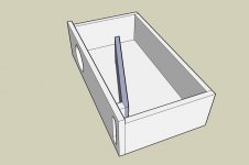
Today I was re-reading the posts in this thread, and I realized that what I drew up on Sketchup yesterday might be upside down. Today I made another attempt. I would appreciate comments on which of these is correct ( if indeed either one is ).
I made a small change on this one and made the baffle 8" wide.
I've deleted the side panel for clarity.
Tweeter also not shown.
John
Attachments
First, I wish to thank GM.......
Specifically does the work I've done reflect what your vision would be, given a 7" cabinet width and dimensions you posted?
How much ( if indeed any ) "fudge" factor can I include when I actually build these?
You're welcome!
The latest one does if you turn it over, so that the vent is at the bottom, though I didn't envision folding it
, though obviously you can.Since a sub is required, you probably won't need to tune the vent, but a +/-10% taper is acceptable with bigger terminus = higher tuning and vice versa.
Anyway, looking forward to reviews of both pipe designs. Just looked at the kit, $59/pr + assembled XOs, what a deal!
GM
Thanks Mucho GM,
I appreciate your ... Err ... turning me around.
Does it really matter whether the vent is top or bottom? I set it that way to give me more room to mount the tweeter above the driver. It can be turned either way ( I have a contingency plan already).
As to the vent opening, it's one thing you didn't spec in your original post, in both the drawings I drew the opening is equal ( +/- ) to the SL of the pipe. If I could trouble you for your best guess as to vent area, I would be able to start smaller and enlarge as needed to tune to taste, along with the stuffing. One of the reasons I drew it as I did was to allow me to make the rear panel removeable and the vent opening adjustable. I was thinking, after reading some of the material on Mr. Dlugos original TL site, of starting roughly with the driver Sd or a little smaller and enlarging as needed. Would you consider this a reasonable course of action?
Again thanks for your replies, and help.
John
I was thinking, after reading some of the material on Mr. Dlugos original TL site, of starting roughly with the driver Sd or a little smaller and enlarging as needed. Would you consider this a reasonable course of action?
Mr. Dlugos is my dad... i'm dave.
The bit you were reading is classical design. It is there for historical reasons and there is a warning somewhere -- probably at the top of the page -- that it has totally been supplanted by proper modeling.
dave
Dave,
Thanks for your reply, I knew of the disclaimer, read it, understood. I've tried to grok the Martin King Mathcad models, I end up wanting to take a nap... I'm severely mathematically challenged, best I ever did was to understand algebra. Very frustrating for someone who wanted to be an engineer as a youth. We all have our limitations.
John
You're welcome!
I don't have to guess, 'SL' is the vent.
GM
Roger that. your comment re: folding, got my juices circulating, since I would have to build a stand anyway.....
If I do a straight line does it matter if the vent faces front or back? ( would there be a cancellation issue?)
John
Hmm, if you understand algebra, you're less math challenged than me and I had a pretty decent career as a 'jack o' trades, master of none' engineer, though with no degree I was officially an applications engineer and of course didn't make the big bucks, but then I didn't have the big responsibilities either, so a more than fair trade for me.
Anyway, FWIW, with this pipe length/driver location, I envisioned 'SL' to just be an open bottom spaced up as required once any vent adjustment was done (if any) such as increasing it in the form of a rectangular duct extension to tune it lower/roll it off to better blend in-room. This has worked very well for me. If mounted on a panel, then changing the opening is required which to some extent defeats the point of using a TQWT.
This also allows some external vent damping if the floor is carpeted, otherwise experimenting with small accent rugs or carpet samples is a good plan. If mounted on a panel, then varying the vent's damping thickness and/or material can be a somewhat tedious affair as well as the need to contain it and/or make it either WAF and/or child, pet 'proof'.
Bottom line, no matter which way the terminus faces, with any form of TL there's strong pipe harmonics that must be damped to keep them from audibly comb filtering with the driver's output, so it's the builder's call to decide what will work best overall in his app.
GM
I've received my kit's, and done some more "design"work and am ready to make sawdust.
I even received approval from SWIMBO for the "look". Strangely she also approved of the iBIB design too. I'll have to post that in the BIB thread when it's farther along too.
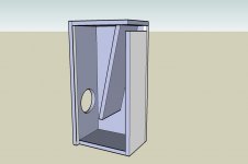
Anyway, barring any gaping fubar mistakes, this is how I am planning to build them. I am planning to extend the brace in the center to behind the magnet of the woofer, as well as use it to mount the XO. The back ( ommited for clarity ) will stop at the end of the rabbet in the sides ( where the vent terminates ).
John
I even received approval from SWIMBO for the "look". Strangely she also approved of the iBIB design too. I'll have to post that in the BIB thread when it's farther along too.
Anyway, barring any gaping fubar mistakes, this is how I am planning to build them. I am planning to extend the brace in the center to behind the magnet of the woofer, as well as use it to mount the XO. The back ( ommited for clarity ) will stop at the end of the rabbet in the sides ( where the vent terminates ).
John
Attachments
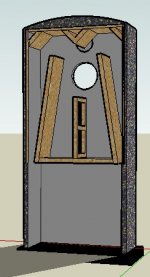
GM, Thanks once again for your wisdom.
I had left the body of the design 1/2" forward of the plinth back to, in my mind allow several X the area of the vents, to avoid that, it did not enter my mind that the other part would act that way. This is why I'm asking these questions before I make sawdust.
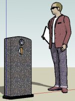
If I understand you correctly, all I will have to do is to change the design to a central column leaving the vents free to operate into totally free space, and otherwise the layout might pass muster? At least I already knew better than to put anything directly in front of the vents as that would tend to mass load them...
Does this look a little better?
John
I had left the body of the design 1/2" forward of the plinth back to, in my mind allow several X the area of the vents, to avoid that, it did not enter my mind that the other part would act that way. This is why I'm asking these questions before I make sawdust.
If I understand you correctly, all I will have to do is to change the design to a central column leaving the vents free to operate into totally free space, and otherwise the layout might pass muster? At least I already knew better than to put anything directly in front of the vents as that would tend to mass load them...
Does this look a little better?
John
Attachments
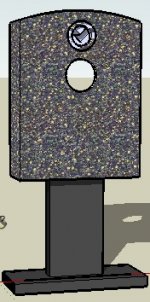
I see no reason why not, but I'm a big believer in optimizing vent tuning, so ideally it would have an adjustable plinth between the speaker and column.
What I had in mind if it wasn't simmed though, would be to have no fixed front panel below the speaker's terminus with a fixed grill cloth covering wrapped around it and the sides with a rear removable pegboard panel to start with and experiment with different open areas if need be. If all goes well, then only the bottom and one side of the cavity will need some damping to quell its cavity resonances.
Another option would be to leave the baffle solid and add a slit vent just below the terminus and if need be, a 'plinth' underneath it. either way, only the only the bottom and one side of the cavity will need some damping to quell its resonances.
GM
I just spent the last 4 hours rifling through my music collection to play this and that on my new speakers.
I built the GM TL design as outlined earlier in this thread. In the end I went with simple, and used a single fold with the vent at the bottom rear. The cabinets ended up being about 8" wide, and 12" deep by ~23" tall. I still have some adjusting to do on the stuffing, but I must say I'm enjoying them. they aren't the best sounding speaker I've ever heard, but they are very listenable, reasonably detailed, and have limited though wonderful bass. There really is something to the TL bass. I think I will add some more stuffing in an attempt to " tighten " the bass up a tiny bit. Truthfully the only piece I played that I missed the really low bass on was "Also Spracht Zarathustra". I have a 30+ YO pressing of the Berlin Philharmonic recorded in a Bavarian church with an 1850's pipe organ. Everything else I played was jazz, and rock/blues. They sounded better for having a few hours on them when I stopped to post.
Thanks again to GM for posting the parameters of the design.
I built these cabinets out of cheap sheet goods to test them, now I've got to get up off some dough for the good stuff and build the real deal.
John
Whatever your particular flavor, have a happy holiday season, be safe.
You're welcome!
I don't have to guess, 'SL' is the vent.
GM
Really? I was under the impression So was the vent......
- Status
- This old topic is closed. If you want to reopen this topic, contact a moderator using the "Report Post" button.
- Home
- Loudspeakers
- Multi-Way
- Vifa Recession Buster kit Transmission Line