Hello Soongsc,
If the input parameters are well known then Hornresp is pretty accurate to simulate axisymetrical horns.
Calculation of the acoustical impedance presented by the horn at its throat to the driver is the main purpose of such software as the other curves like response, phase, etc need the knowledge of the acoustical impedance.
We can see how accurate is Hornresp in looking at the comparison between measured and predicted acoustical impedance. (Unfortunately acoustical impedance is pretty hard to measure without a well equipped laboratory )
David McBean gave few example of comparison between measured acoustical impedance curves and predicted. See:
- - - - - - - - - - - - - - - - - - - - - - - - - - - - - - - - - - - - - -
for an exponential horn
. . . . . measurements
http://www.diyaudio.com/forums/attachment.php?s=&postid=1524736&stamp=1212155433
. . . . .as predicted by Hornresp
http://www.diyaudio.com/forums/attachment.php?s=&postid=1524742&stamp=1212155580
- - - - - - - - - - - - - - - - - - - - - - - - - - - - - - - - - - - - - -
for a tractrix horn
. . . . . measurements
http://www.diyaudio.com/forums/attachment.php?s=&postid=1524740&stamp=1212155510
. . . . . as predicted by Hornresp
http://www.diyaudio.com/forums/attachment.php?s=&postid=1524743&stamp=1212155659
- - - - - - - - - - - - - - - - - - - - - - - - - - - - - - - - - - - - - -
Generally when designing a horn we want the resistive part of the acoustical impedance the most constant.
Electrical impedance is another animal and as the horn influences the electrical impedance of the driver near its acoustical cut-off frequency but don't modify the electrical impedance at high frequency, I guess that it is quasi impossibe to design a horn to obtain a constant electrical impedance.
Most probably a series of tuned pipes of various length may be more adapted to reach such goal.
Best regards from Paris, France
Jean-Michel Le Cléac'h
soongsc said:
Thanks Jean-Michel,
Do you think it's technically possible to design a countour profile such that the impedance is almost flat? I haven't been able to understand the setting of Hornresp. How close is it to actual measurements?
Hello,
The knowledge of the acoustical impedance of the horn should be the basis to the choice of Fc. We want the horn to have the most resistive impedance inside the desired interval of frequency to reproduce.
As it is very difficult for an hobbyist to measure the 2 parts of the acoustical impedance (acoustical resistance and acoustical reactance) I prefer myself to choose Fc after the study of the group delay curve of the horn (mounted on a driver able to reproduce the desireable range of frequency).
I obtain the group delay curve by derivation of the phase curve which one, in parallel to the response curve, is obtained by my own Matlab routine that is based on Discrete Fourier Transform (DFT) and not FFT (with DFT you can place the origin of time at the arrival of the pulse so then it is far more easy to unwrap the phase than with FFT).
I express the group delay in equivalent distance travelled at the speed of sound (c = 341 to 344 m/s).
For my own use I only use horns above frequency for which the group delay is less than 8 centimeters. Doing this I am sure that the harmonics and fundamental keep their initial phase relations at best in the reproduced range of frequency.
With Le Cleac'h horns this leads to use a high pass crossover at 2.5 to 3 times the cut-off frequency of the horn.
Best regards from Paris, France
Jean-Michel Le Cléac'h
serenechaos said:Hello Jean-Michel,
How do you actually choose the horn Fc for desired frequency range?
(What will load the driver best).
Roughly half an octave to an octave below the lowest frequency you want to play through the given horn?
Thank you,
Robert
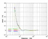
Hello Eva,
You'll find in attached file, group delay curves for one of my TAD TD2001 on a Le Cléac'h horn (Fc = 320Hz).
(group delay on this graph is expressed, as I am accustomed to, in equivalent distance travelled at the speed of sound, so it is given in meters).
There is 3 curves to show the influence of a series resistor.
(a large series resistor or better a current source fills the famous hole at 1600Hz on the TD2001curves, the origin of which is explained in Kinoshita's paper in JAES and this as also its infleunce on the group delay curve in the interval 1300Hz -2000Hz.)
Best regards from Paris, France
Jean-Michel Le Cléac'h
Eva said:Could you show us some sample group delay plots from real horns? I'm very interested.
I use equalization to flatten group delay down to the cutoff frequency but I can't currently measure it, I can only estimate it indirectly.
Attachments
Moving away from cut off frequency.
I just found this thread and wanted to thank the participants, especially JMMLC. When I was implementing the crossovers I found that moving away from the cut off of the upper horn, 250hz, had decided sonic benefits although it seemed a waste to have a larger horn than was being used. After JMMLC post on this here in this thread I can understand much better why I heard what I heard. When I design crossovers I measure and listen, measure and listen, the ear always finds things the measurements do not. This information has just saved me a lot of effort as I was about to try a smaller horn. Instead, it seems that a similar frequency elliptical horn would be a better choice. Many Thanks.
I just found this thread and wanted to thank the participants, especially JMMLC. When I was implementing the crossovers I found that moving away from the cut off of the upper horn, 250hz, had decided sonic benefits although it seemed a waste to have a larger horn than was being used. After JMMLC post on this here in this thread I can understand much better why I heard what I heard. When I design crossovers I measure and listen, measure and listen, the ear always finds things the measurements do not. This information has just saved me a lot of effort as I was about to try a smaller horn. Instead, it seems that a similar frequency elliptical horn would be a better choice. Many Thanks.
If you hear things you aren't measuring, you aren't taking the right measurements. This effect is easy to measure. Jean-Michel has just shown it in the previous post as group delay. I've measured something similar as stored energy similarly to how Linkwitz does. See: http://ldsg.snippets.org/HORNS/storede.html
- Status
- This old topic is closed. If you want to reopen this topic, contact a moderator using the "Report Post" button.