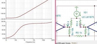
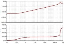
Watch out for common-mode instability! If the amplifiers are not unity-gain stable, you have to attenuate the common-mode feedback.
For example, you could split R5 in two pieces and put an RC network to ground from the centre point. You can choose R and C by looking at the common-mode loop gain.
I used essentially this feedback configuration in a direct-drive amplifier for electrostatic loudspeakers, see https://www.diyaudio.com/community/threads/looking-for-high-voltage-tubes.408467/post-7583684
Last edited:
These Chinese chip amps are simply not worth thinking about. In all aspects they are worse than something like a LM3886 or TDA7289 and miss vital features of modern chips. Please remeber you are posting in a HIFI forum.
The money you pretend to save, is spent on additional parts and safety devices. Apart from this, you can add as many parts as you like, the sound will always be sub average.
If you want a child's toy plastic duck to quak really loud, use these chips from China, but don't pay 20 Cent each, 5 Cent should do.
PS did I mention they are notorious unreliable and many fail for no obvious cause?
I always thought it was a DIY forum...Please remeber you are posting in a HIFI forum.

This!Watch out for common-mode instability! If the amplifiers are not unity-gain stable, you have to attenuate the common-mode feedback.
Also, the common-mode voltage -- 1/2 of the unbalanced input voltage -- is not removed, that is, the output is not symmetric.
@HAYK
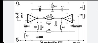
In the end it is just the first stage of a standard 3-OpAmp instrumentation amplifier, drawn obscurely.
In my circuit, as it doesn't have differential input, the inverter has a gain Rf/R and the non inverter has a gain (Rf+R)/R this why the inverter is 11k vs 10k.
On Google I found this but the site is closed. The Russian one used a known chip.
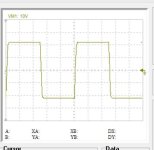
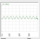
Added bellow 10khz square wave on the load.
On Google I found this but the site is closed. The Russian one used a known chip.
Added bellow 10khz square wave on the load.
Attachments
Last edited:
Ah, OK, I missed the resistor imbalance.In my circuit, as it doesn't have differential input, the inverter has a gain Rf/R and the non inverter has a gain (Rf+R)/R this why the inverter is 11k vs 10k.
Both amps are working with a gain of 11. But the Chinese chips are unity stable that I will use 4 parallel on each side driven by these two. I must check the maximum input voltage if it is less than the dropout of the driver.
Suppose that due to some disturbance or other, the outputs of both amplifiers in post #1 increase by 1 uV. The voltages at both inverting inputs then also increase by 1 uV, rather than 1/11 uV. Hence, common-mode disturbances are fully fed back.
- Home
- Amplifiers
- Chip Amps
- Very simple bridge, has seen already?