Not superior at all. I set myself a constraint of 3 BJTs and once I decided on CFP output I'd used all 3. A 4 BJT amp would deserve a new thread I think.Mark + Mark, out of genuine curiosity to learn, Iam wondering why the choice of a passive load in the output stage is considered superior to a current source? I'm not disputing this choice just seeking clarification.
Its believed to be THD+noise, rather than the sum of the components you requested, but it can be less or more than the first figure. Its clearly calculated differently somehow, for instance it can be smaller than the 2nd harmonic, so perhaps it is calculated using a quicky/dirty method.Whilst I'm at it, I have a question about LTspice. What is the figure in brackets with regards to THD?
If you replaced the resistor with a current source the amplifier would now have four transistors. "3BJT" would no longer be true. That may be one reason why designers of 3BJT circuits tend not to include constant current source loads at the very output.
Fair enough.
Cool thread idea. I'm just working through it.
It's nice to see simple projects, and improve upon them, minimally.
TIP41/42 isnt really a bad device, old perhaps, and slow too, but I had fun making a PP output stage for LF351 using them.
Never got around to measuring the THD of that little lunchtime project - it would be interesting to compare
It's nice to see simple projects, and improve upon them, minimally.
TIP41/42 isnt really a bad device, old perhaps, and slow too, but I had fun making a PP output stage for LF351 using them.
Never got around to measuring the THD of that little lunchtime project - it would be interesting to compare
Just wondering whether BD139/140 would be appropriate / better / worse in lieu of the TIP41/42?
Any thoughts?
The first version I built of this circuit used 2 bd139's on small heatsinks. Heatsinks would be recommended as I don't think they can handle much power without.
It's hard to say whether they were better or worse because I operated the TIP41 circuit at a higher current which would have made it perform better in itself.
Last edited:
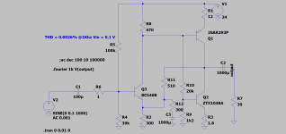
Nice. I got 0.0095% but at a higher input of 0.5V. I think all of the circuits so far are pretty sensitive to supply voltage for proper biasing, getting independence from the supply and low distortion and good push-pull output drive is perhaps more than 3 transistors can manage?
Getting good sound out of a 2 transistor headphone amplifier is every bit as challenging as 3. Try it!
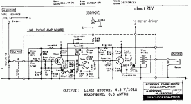
There's also the 1-Q Challenge. The TEAC solution sounded fine, but needed hot low-Z phones to be even moderately loud. This is how I got into many-milliWatt HP amps.
Hmmmm... 0.4% DC efficiency (73mW DC for 0.3mW audio).
Attachments
- Status
- This old topic is closed. If you want to reopen this topic, contact a moderator using the "Report Post" button.
- Home
- Amplifiers
- Headphone Systems
- Very Simple 3BJT Headphone Amplifier