I have just done and, at the risk of seeming crazy, i'm not still sure that the MJL4281A sounds better than the TIP142. It sounds clearer, but not as lovely "tubby" as the original did sound.
I still have to try to run the output open-loop and correct offset with a dc-servo to see if it gets even more "tubby".
I still have to try to run the output open-loop and correct offset with a dc-servo to see if it gets even more "tubby".
eketehe said:I'm done n test my mono,
hmm the detail is so promising..
I think i only have about 10 watt. I have to done my stereo for full result
You did it?
 What transistors? Do you like it? It is designed for high efficiency speakers... this amp at 10W in 97 dB's fullranges would sound as loud as a 200W amp in common 84 dB loudspeakers.
I have just finished one channel of my one with MJL4281A transistors and... i'm not very enthusiastical about it. The driver stage was also single ended / ccs-loaded at a hot 100mA.
The one using the tip-142 sounded like tubes in the very best sense. This looks very, very nice on the scope but its more harsh and not as lovely to listen. Not happy since these transistors cost four times the price of the tip's.
The comparison may not be fair since i also did a mosfet-sziklai in the middle which promised extreme techical performance but was so painfully detailed that i stored it to impress friends, so i may have forgotten how did actually sound the first one.
I hope to have time and money to assemble and enclose the three (mains wiring is a textbook example of what nobody should ever try) and do a fair a/b/c comparison.
I would love to read your opinion eketehe, as detail is not what i found to be the most remarkable of the amp, but rather "warmth" or musicality.
PURE AND TRUE
other comment will heard like yours.
actualy, lately i got my soldering time becomes a bit rare, and
we'll be in other main busy in this near future.
so within this 2 days, i will in rush to put my stereo proto.. i mean your proto, onto a semi permanent case. so we're able to enjoy during our busy.
complete result will be in the day after tomorrow. i was test em' on 4ohm speakers, which i'm not dare enough to play over 5 minutes, and describe sounding fair and toroughly. but from flash hearing it shows a natural sound, expecialy human voices will shows something like your old signature.
Great!
Re: PURE AND TRUE
Playing in 8 ohm will restrict output power and increase dissipation at the upper transistor, but it will also decrease heat generated on the bottom one. Anyways, the design is optimized for 8 ohms.
To run it on 4 ohms you should set the current at I = sqrt(2*P/Z) where P is the desired power outputby choosing the 0.5 resistors to be (1.4/I). You should also lower the voltage to reduce dissipation. The voltage should be V = sqrt(2*Z*P) + 2 on both rails. Z should be choosen as the minimum impedance dip for the loudspeakers at the current expression. The voltage one is fine with nominal impedance. That's why fullranges that don't go below it's nominal impedance are great here. ( * )
I have found that amps have some sort of compromise between how accurate and perfect you want them to sound and how confortable it will be to listen to background music with them.
The design is not mine in fact, it is a very common circuit, but i have found the combination of a high fidelity opamp and a slow output stage transistors to be quite pleasant, but that's a matter of taste.
That's one of these things you can only get if you diy, commercial designs will either have low-quality drivers with cheap output transistors or high-quality drivers with high quality output transistors. I'm sure that there are better choices for the output-opamp combination, so you are invited to try others for yourself and comment the results.
I'm glad that you like it.
EDIT ( * ) Voltage should never exceed 17V at the opamp and the voltage and current of the output transistors should not be pushed very much. I'm sure you have already realized how hot it gets!
eketehe said:
other comment will heard like yours.
actualy, lately i got my soldering time becomes a bit rare, and
we'll be in other main busy in this near future.
so within this 2 days, i will in rush to put my stereo proto.. i mean your proto, onto a semi permanent case. so we're able to enjoy during our busy.
complete result will be in the day after tomorrow. i was test em' on 4ohm speakers, which i'm not dare enough to play over 5 minutes, and describe sounding fair and toroughly. but from flash hearing it shows a natural sound, expecialy human voices will shows something like your old signature.
Great!
Playing in 8 ohm will restrict output power and increase dissipation at the upper transistor, but it will also decrease heat generated on the bottom one. Anyways, the design is optimized for 8 ohms.
To run it on 4 ohms you should set the current at I = sqrt(2*P/Z) where P is the desired power outputby choosing the 0.5 resistors to be (1.4/I). You should also lower the voltage to reduce dissipation. The voltage should be V = sqrt(2*Z*P) + 2 on both rails. Z should be choosen as the minimum impedance dip for the loudspeakers at the current expression. The voltage one is fine with nominal impedance. That's why fullranges that don't go below it's nominal impedance are great here. ( * )
I have found that amps have some sort of compromise between how accurate and perfect you want them to sound and how confortable it will be to listen to background music with them.
The design is not mine in fact, it is a very common circuit, but i have found the combination of a high fidelity opamp and a slow output stage transistors to be quite pleasant, but that's a matter of taste.
That's one of these things you can only get if you diy, commercial designs will either have low-quality drivers with cheap output transistors or high-quality drivers with high quality output transistors. I'm sure that there are better choices for the output-opamp combination, so you are invited to try others for yourself and comment the results.
I'm glad that you like it.
EDIT ( * )
Voltage should never exceed 17V at the opamp and the voltage and current of the output transistors should not be pushed very much. I'm sure you have already realized how hot it gets!Dxvideo said:Ok..
What about my "BJT as a gate driver" idea (like darlington)? This can reduce the capacitive affects, isnt it?
I built a similar amp using a mosfet sziklai output stage (details here: http://www.diyaudio.com/forums/showthread.php?s=&threadid=124627 ) Extraordinary detail, but i found it a tad annoying. I will post a new design once i get new loudspeakers to judge better.
a newbie done his very first class A
Hi There Mr Ion,
Now i have a very nice sounding amplifier to drive the biger 3way (12'W/6'M/2'T 8R0 ) . loud enough. Thanks to you Mr Ionomolo =).
its identicaly with your schematic, only 100uF for C12, BC550C for Q3, and
3K3 at R3.
a stereo monoblocks, runs with whatever available parts with +/-16VDC
coming from 12-0 12-0 ( separated CT ) 5A EI, 8 X IN5404 30KuF carlos FM's design/chanel, in a used 30x40x15cm metal case.
I wish i'm a smarter to offer you some good input for your development,
altough i already satisfied.. but OK, i will try for other experiment, as
it also planed to placed in a new cabinet, and this is fun anyway.
before going further, as promised, here are some newbie questions :
related with constant current requirement.. hows are diodes works? i mean
the conversion AC to DC ordered by load ( pull ) or trafo capacity ( push)?
IN5404 capacity is 3A, and bridged 4 IN5404 capacity is still 3A right?
what is the buffer( LM4562) use for? for a 'plug n play' can we do a little pass lab-ing work here?
i'm be advsd tht the TIP142 is the only available darlington here.. what is darlington anyway? how about pair of metal oxides in Q6, Q7?
currently i'm placed the LM4562, i still have other eight leged LM833, TL072, NE5532/4 which i will try 'em later. i was thought to add more voltage ( 23 - 24V ) and regulate the chip at 18V.. but just forget it as i also forget about the small and simple cabinet design, since realized that the current heat was
as hot as hell!.
hey i just find the biger heatsink, darn... they're expensive!
i can see that you're a vvhi-fi person,
for its been 2 days i amaze my new lm4562+classA amp, and haven't heard anyspeed problem as issues =).
This is my first class A, which honestly i built this for this is the
simpliest design, I'm not a right person to judge and compare with other class A, but yes this is much nicer than my previous chipamps. .. dynamics, fidelity,clarity and pretty clean..ah not hard for that.
this also confirm me again that monoblocs have greater succes percentage to avoid humm or noises, and the E1 tranfos not so critical. this amp is zero humm and noises.
do you know a chip amp which internaly runs class A?
i read the safety................... tittled thread, so how you
get succes with laptop PSU? thats cud be a great help, my cabinet weighted about over 10Kgrams. thats the HEAVIEST for about 10 watt amp.
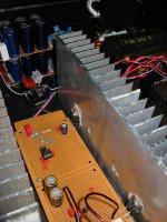
Attachments
Re: a newbie done his very first class A
If you can find two supplies you only have to buy a couple that have sufficient current rating at 16-17V and that aren't safety earthed (2-connections plug). Then you have two options: buy two female dc connector to place at the enclosure or cut the wires. It is better to place the connectors because you can keep the warranty of the supplies. If the loudspeakers aren't very sensitive then you should not hear any noise. If the character of the noise changes when you place your ear close to the loudspeaker from what you did hear with the unregulated supply then you can try wounding the wire arround a ferrite, adding a choke in series with the input and adding a cap before and after the choke. If you do everything there should be no noise at all. The impedance of the psu should be low at low frequencies and at high frequencies all the current should pass through the on-board filtering caps. If you want to add high capacity to an smps i would add a soft-on mechanism. It can be done very easily with a zener, two resistors a transistor and a relay. If the psu has current limiting because it limits the switching duty cycle this would be useless because the limit in the duty cycle itself protects the psu from "everything", but you don't know what's inside the psu. I would love to hear from an expert about that.
The LM4562 is not a buffer, it is an opamp. In particular the LM4562 does not sound very well as a buffer. It sets the gain and controls the output stage distortion and offset. If you remove it the amp will have unity gain and 1.4V offset. A very bad idea.
If you own a scope you will notice that the output looks nasty. This can be solved by placing a resistor between 100K and 470K in parallel with the output transistors (start with the bigger and then go down). but it does not change the sound so if you don't have the scope i won't worry because you will hear the same.
I found the sound from this amp to be "unfocussed". This is not bad at all, in fact this makes me prefer it to much more sofisticated designs. If i place two loudspeakers at 20 cm or so i can't tell which one is playing from 2 m from them. It's surrounding and nice, but it does not have "imaging". I'm building a mosfet one that i will use for "focused listening" and i will keep it to play music in the background while working or reading, because it is among the least intrusive amps i've heard. No soundstage, no air, no speed, no audiophilia, just nice music, which is hard to get if you go "megalow THD megahigh feedback gigahertz speed class B".
You can also drop-down replace the upper TIP142 with a MJL4281A. If you do the maths you will notice that it will place a stress on the opamp slightly above its rated output (not above "absolute maximum ratings") because it has less current gain. This produces a huge change in sound (changing transistors is not subtle as changing other parts). The sound becomes much more solid, it seems clearer but it's also more harsh. I prefer the soft tips because they sound closer to tubes.
At the moment i'm working in a mosfet prototype that has a clarity that is beyond anything i've heard before (0.0018 % THD worst case [20KHz, maximum output] 0.0025 % 50 KHz Maximum output, THD 0.3% at 1 MHz full output, all open-loop), but it does not have the "tubeness" of the bjt one.
There are no chipamps that work in class A because the chipamp package makes it very difficult to extract the heat, but you can bias an LM3886 in class A as long as you provide the immense heatsink (and perhaps the fans) to ensure that spike will never act. T
I plan to buld and recommend the LM3886 class A amp for a reason: It has a quasi-complementary output stage. This means that if you place a constant current sink at it's output you will get a classs A emmitter-follower amp like this, but if you place a constant current source you will get a Sziklai output stage. It does not seem silly to place a switch to choose between EF and Sziklai (CFP) because the source and sink will never operate at the same time so they can be placed on the same heatsink (the expensive part) and having the two options will requiere an extra investment of $2.5 + switch (this can be anything from free to very expensive depending on aesthetics).
You will not get louder sound if you supply the transistors above 19V, so it's not a good idea to do so.
I feel that the rating of 3A is very low for the diodes. If you read the thread about the power supplies you have seen my spice simulation about transient currents in rectifiers. As other members pointed out the result is exagerated as it does not take into account the resistance of the secondary, but the peak currents will always be higher than the current demand of the amp. I suggest to go for a 10A minimum as the increase in price is not high (maybe $0.5/$1) and a failure can ruin the whole amplifier (I had that experience with a bpa200 and it is not funny).
eketehe said:Hi There Mr Ion,
Now i have a very nice sounding amplifier to drive the biger 3way (12'W/6'M/2'T 8R0 ) . loud enough. Thanks to you Mr Ionomolo =).
its identicaly with your schematic, only 100uF for C12, BC550C for Q3, and
3K3 at R3.
a stereo monoblocks, runs with whatever available parts with +/-16VDC
coming from 12-0 12-0 ( separated CT ) 5A EI, 8 X IN5404 30KuF carlos FM's design/chanel, in a used 30x40x15cm metal case.
I wish i'm a smarter to offer you some good input for your development,
altough i already satisfied.. but OK, i will try for other experiment, as
it also planed to placed in a new cabinet, and this is fun anyway.
before going further, as promised, here are some newbie questions :
related with constant current requirement.. hows are diodes works? i mean
the conversion AC to DC ordered by load ( pull ) or trafo capacity ( push)?
IN5404 capacity is 3A, and bridged 4 IN5404 capacity is still 3A right?
what is the buffer( LM4562) use for? for a 'plug n play' can we do a little pass lab-ing work here?
i'm be advsd tht the TIP142 is the only available darlington here.. what is darlington anyway? how about pair of metal oxides in Q6, Q7?
currently i'm placed the LM4562, i still have other eight leged LM833, TL072, NE5532/4 which i will try 'em later. i was thought to add more voltage ( 23 - 24V ) and regulate the chip at 18V.. but just forget it as i also forget about the small and simple cabinet design, since realized that the current heat was
as hot as hell!.
hey i just find the biger heatsink, darn... they're expensive!
i can see that you're a vvhi-fi person,
for its been 2 days i amaze my new lm4562+classA amp, and haven't heard anyspeed problem as issues =).
This is my first class A, which honestly i built this for this is the
simpliest design, I'm not a right person to judge and compare with other class A, but yes this is much nicer than my previous chipamps. .. dynamics, fidelity,clarity and pretty clean..ah not hard for that.
this also confirm me again that monoblocs have greater succes percentage to avoid humm or noises, and the E1 tranfos not so critical. this amp is zero humm and noises.
do you know a chip amp which internaly runs class A?
i read the safety................... tittled thread, so how you
get succes with laptop PSU? thats cud be a great help, my cabinet weighted about over 10Kgrams. thats the HEAVIEST for about 10 watt amp.
If you can find two supplies you only have to buy a couple that have sufficient current rating at 16-17V and that aren't safety earthed (2-connections plug). Then you have two options: buy two female dc connector to place at the enclosure or cut the wires. It is better to place the connectors because you can keep the warranty of the supplies. If the loudspeakers aren't very sensitive then you should not hear any noise. If the character of the noise changes when you place your ear close to the loudspeaker from what you did hear with the unregulated supply then you can try wounding the wire arround a ferrite, adding a choke in series with the input and adding a cap before and after the choke. If you do everything there should be no noise at all. The impedance of the psu should be low at low frequencies and at high frequencies all the current should pass through the on-board filtering caps. If you want to add high capacity to an smps i would add a soft-on mechanism. It can be done very easily with a zener, two resistors a transistor and a relay. If the psu has current limiting because it limits the switching duty cycle this would be useless because the limit in the duty cycle itself protects the psu from "everything", but you don't know what's inside the psu. I would love to hear from an expert about that.
The LM4562 is not a buffer, it is an opamp. In particular the LM4562 does not sound very well as a buffer. It sets the gain and controls the output stage distortion and offset. If you remove it the amp will have unity gain and 1.4V offset. A very bad idea.
If you own a scope you will notice that the output looks nasty. This can be solved by placing a resistor between 100K and 470K in parallel with the output transistors (start with the bigger and then go down). but it does not change the sound so if you don't have the scope i won't worry because you will hear the same.
I found the sound from this amp to be "unfocussed". This is not bad at all, in fact this makes me prefer it to much more sofisticated designs. If i place two loudspeakers at 20 cm or so i can't tell which one is playing from 2 m from them. It's surrounding and nice, but it does not have "imaging". I'm building a mosfet one that i will use for "focused listening" and i will keep it to play music in the background while working or reading, because it is among the least intrusive amps i've heard. No soundstage, no air, no speed, no audiophilia, just nice music, which is hard to get if you go "megalow THD megahigh feedback gigahertz speed class B".
You can also drop-down replace the upper TIP142 with a MJL4281A. If you do the maths you will notice that it will place a stress on the opamp slightly above its rated output (not above "absolute maximum ratings") because it has less current gain. This produces a huge change in sound (changing transistors is not subtle as changing other parts). The sound becomes much more solid, it seems clearer but it's also more harsh. I prefer the soft tips because they sound closer to tubes.
At the moment i'm working in a mosfet prototype that has a clarity that is beyond anything i've heard before (0.0018 % THD worst case [20KHz, maximum output] 0.0025 % 50 KHz Maximum output, THD 0.3% at 1 MHz full output, all open-loop), but it does not have the "tubeness" of the bjt one.
There are no chipamps that work in class A because the chipamp package makes it very difficult to extract the heat, but you can bias an LM3886 in class A as long as you provide the immense heatsink (and perhaps the fans) to ensure that spike will never act. T
I plan to buld and recommend the LM3886 class A amp for a reason: It has a quasi-complementary output stage. This means that if you place a constant current sink at it's output you will get a classs A emmitter-follower amp like this, but if you place a constant current source you will get a Sziklai output stage. It does not seem silly to place a switch to choose between EF and Sziklai (CFP) because the source and sink will never operate at the same time so they can be placed on the same heatsink (the expensive part) and having the two options will requiere an extra investment of $2.5 + switch (this can be anything from free to very expensive depending on aesthetics).
You will not get louder sound if you supply the transistors above 19V, so it's not a good idea to do so.
I feel that the rating of 3A is very low for the diodes. If you read the thread about the power supplies you have seen my spice simulation about transient currents in rectifiers. As other members pointed out the result is exagerated as it does not take into account the resistance of the secondary, but the peak currents will always be higher than the current demand of the amp. I suggest to go for a 10A minimum as the increase in price is not high (maybe $0.5/$1) and a failure can ruin the whole amplifier (I had that experience with a bpa200 and it is not funny).
Re: Re: a newbie done his very first class A
Thanks Sir,
The PSU are switching trafos, i think i'll not having them except for test only. they're easily broke. i don't know just not sure.
a bit surprised for 'unfocussed', as i find here is a naturaly detail.
but i agree about the surrounding sound. thats also other advantage, as i confess tht my L/R a bit different. i was DIY a serial crossover network, just great for one chanel but i never made the pair identicly. i think i'm having the 1sttimer euphoria haha
so there are wider specifics goals... NICE
Ok, i've read your writting, i will soon re-do the PSU. maybe using 16 x 6A of phillip stand diode + heatsink. some like 10A KBPC/U or greater 35A never recommended here as the capacity oftently not correct.
i can cee that this amp is a great energy sucker, maybe you will adv the suitable capacitance at PSU for each chanel. a bit shock when someone here says the class a need at least 100.000uF for 20W.
Brgds.
eka
Re: Re: Re: a newbie done his very first class A
With smps you DONT need that capacitance, because the logic on the board ensures low impedance at LF, and the on-board caps will deal with HF. For unregulated operation 20.000 uF gives about 1.5V ripple, while 200.000 uF gives 0.15V. Everybody will tell you that 1.5V is excessive, but if you have such capacitors i'll bet you won't hear an impressive difference.
eketehe said:Thanks Sir,
The PSU are switching trafos, i think i'll not having them except for test only. they're easily broke. i don't know just not sure.
a bit surprised for 'unfocussed', as i find here is a naturaly detail.
but i agree about the surrounding sound. thats also other advantage, as i confess tht my L/R a bit different. i was DIY a serial crossover network, just great for one chanel but i never made the pair identicly. i think i'm having the 1sttimer euphoria haha
so there are wider specifics goals... NICE
Ok, i've read your writting, i will soon re-do the PSU. maybe using 16 x 6A of phillip stand diode + heatsink. some like 10A KBPC/U or greater 35A never recommended here as the capacity oftently not correct.
i can cee that this amp is a great energy sucker, maybe you will adv the suitable capacitance at PSU for each chanel. a bit shock when someone here says the class a need at least 100.000uF for 20W.
Brgds.
eka
With smps you DONT need that capacitance, because the logic on the board ensures low impedance at LF, and the on-board caps will deal with HF. For unregulated operation 20.000 uF gives about 1.5V ripple, while 200.000 uF gives 0.15V. Everybody will tell you that 1.5V is excessive, but if you have such capacitors i'll bet you won't hear an impressive difference.
Re: Re: Re: Re: a newbie done his very first class A
Tks Mr Ionomolo,
I rest this amp a while to rebuilt later with complete planing : biger cabinet, biger heatsinks + fans and maybe some Q development.
Yesterday i got a full day to play this amp, and found that the heat was very rage. i felt that something will ready to melt and bad accident await, as the heat also infiltrate the case ( the heatsink screwed to metal case ).
so the lm1875 hv an extra duty time, and i missed the warmness.
Tks to let me know this, this is nice, i love it.
Brgds.
Eka
ionomolo said:
With smps you DONT need that capacitance, because the logic on the board ensures low impedance at LF, and the on-board caps will deal with HF. For unregulated operation 20.000 uF gives about 1.5V ripple, while 200.000 uF gives 0.15V. Everybody will tell you that 1.5V is excessive, but if you have such capacitors i'll bet you won't hear an impressive difference.
Tks Mr Ionomolo,
I rest this amp a while to rebuilt later with complete planing : biger cabinet, biger heatsinks + fans and maybe some Q development
. Yesterday i got a full day to play this amp, and found that the heat was very rage. i felt that something will ready to melt and bad accident await, as the heat also infiltrate the case ( the heatsink screwed to metal case ).
so the lm1875 hv an extra duty time, and i missed the warmness.
Tks to let me know this, this is nice, i love it.
Brgds.
Eka
Re: Re: Re: Re: Re: a newbie done his very first class A
I'm glad you like it. A zobel network can also increase stability (or not) you can try it if you have the parts on hand. The amp shows some ugly things on the scope that are on the way to be fixed. But i got one "clean" and there was no audible difference other than better clipping (if it is unstable it will be "popcorny").
The "tubby" warmth is pretty exclusive to the tips. I have tried it with transistors costing $5 and requiring an $1 driver and ithey sounded closer to "standard".
eketehe said:
Tks Mr Ionomolo,
I rest this amp a while to rebuilt later with complete planing : biger cabinet, biger heatsinks + fans and maybe some Q development
Yesterday i got a full day to play this amp, and found that the heat was very rage. i felt that something will ready to melt and bad accident await, as the heat also infiltrate the case ( the heatsink screwed to metal case ).
so the lm1875 hv an extra duty time, and i missed the warmness.
Tks to let me know this, this is nice, i love it.
Brgds.
Eka
I'm glad you like it. A zobel network can also increase stability (or not) you can try it if you have the parts on hand. The amp shows some ugly things on the scope that are on the way to be fixed. But i got one "clean" and there was no audible difference other than better clipping (if it is unstable it will be "popcorny").
The "tubby" warmth is pretty exclusive to the tips. I have tried it with transistors costing $5 and requiring an $1 driver and ithey sounded closer to "standard".
eketehe said:Tks again sir,
i'll reconsider also the smps, or somethin like that or like Aloia psu 13.I. I read a writting says that inductive psu(choke) is much better than the capatitive (caps) i'll dig more info n see.
Brgds
eka
This amp is better suited to inductive filtered supplies than a class B counterpart as it draws a constant amount of current in average, but you will also need a certain capacitance to get low supply impedance at low frequencies.
eketehe said:Dear sir,
i find the pps, rated 3,4A 0-16Vdc. i'll consider to buy 4 of 'em for stereo.
I'm just not sure, its not supossed to be earthed right?
For total 13A seems we'll need a softstart network, have any idea?
You won't need a softstart for something that small. The 13A is on the secondary sides.
regards
eketehe said:Dear sir,
i find the pps, rated 3,4A 0-16Vdc. i'll consider to buy 4 of 'em for stereo.
I'm just not sure, its not supossed to be earthed right?
For total 13A seems we'll need a softstart network, have any idea?
If you have decided to use an smps, then you should choose one that is not safety-earthed. These have a drawing of a square inside another square and are equally safe.
They aren't earthed so there will be no ground loops as long as you don't add them.
If you hear any noise, which is not sure, you can add a choke in series with the V+ and V- before the cap, you can also add more capacitance after the choke. There sould be no audible noise then unless you stick your ear to the tweeter.
- Status
- This old topic is closed. If you want to reopen this topic, contact a moderator using the "Report Post" button.
- Home
- Amplifiers
- Chip Amps
- Very nice sounding chipamp-driven working class A amp