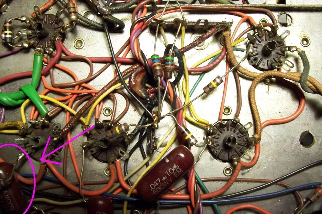
It's the .047 uF cap seen in the lower left corner:
Sprague "Orange Drops" are a pretty cost effective replacement. Use the same exact value as before (.047 uF). I think the 716P and the 715P are both good. One has leads which are easier to bend than the other, but I can't remember which.
http://store.triodestore.com/sprag71ordro.html
If you have to mail order the parts, given the cost of shipping you may as well order four and replace them all.
kevinkr said:Something badly amiss here, it should be wired the same as all the others - incidentally pin 1 is no connection on a 6BQ5/EL84 so if this is where the grid resistor and coupling cap are connected this is the reason why you are having problems with this tube - should be connected to pin 2. Big Oops if true...
I thought we decided a while back that pins 1 and 2 are internally connected on the 6BQ5. At least they must have been on the original Raytheon tubes Kirk had in the amp, or the thing never would have flown in the first place.
It shouldn't be much trouble to move the connections from pin 1 to pin 2, and it probably ought to be done just for the sake of consistency.
Ty_Bower said:It's the .047 uF cap seen in the lower left corner:
Sprague "Orange Drops" are a pretty cost effective replacement. Use the same exact value as before (.047 uF). I think the 716P and the 715P are both good. One has leads which are easier to bend than the other, but I can't remember which.
http://store.triodestore.com/sprag71ordro.html
If you have to mail order the parts, given the cost of shipping you may as well order four and replace them all.
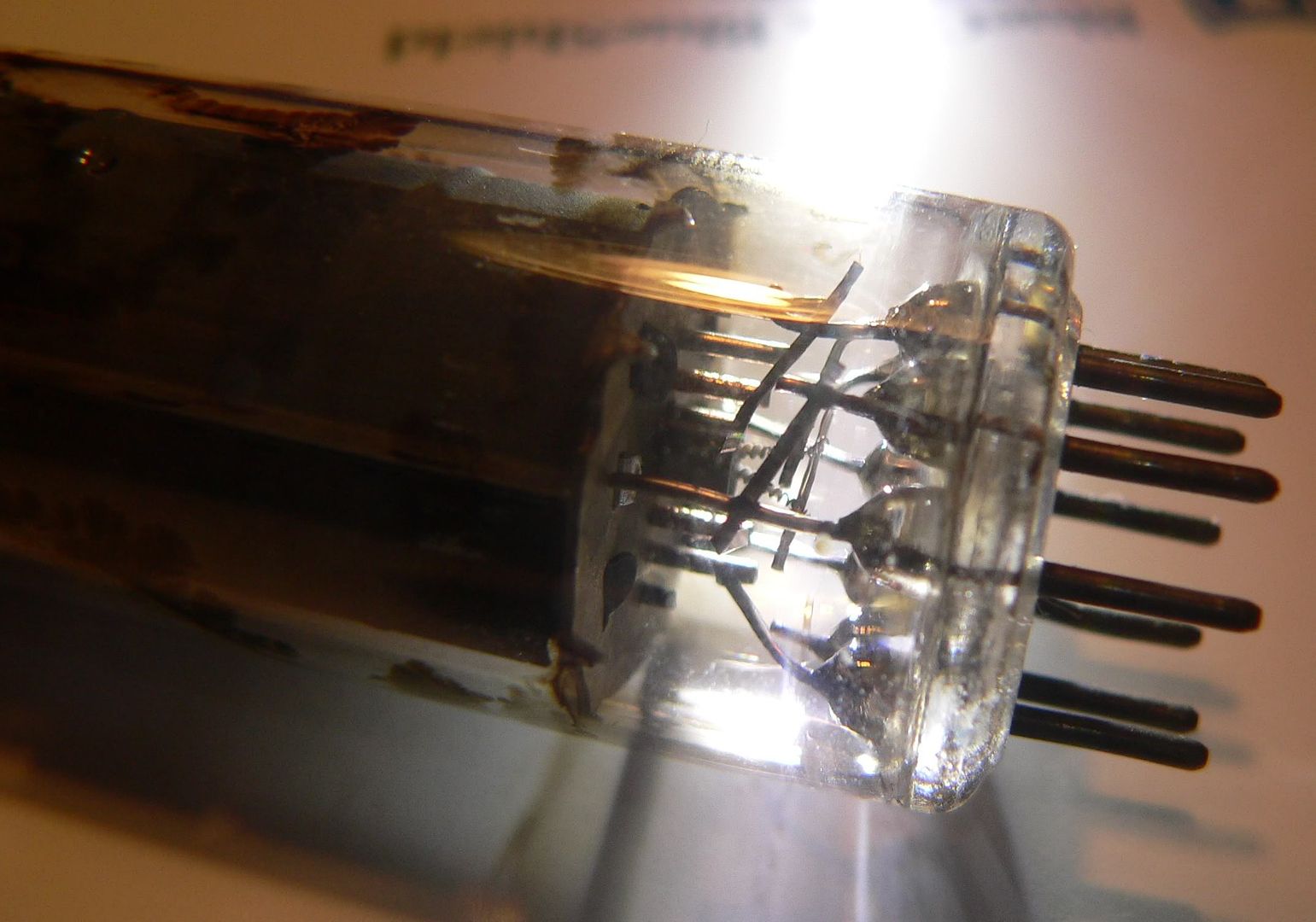
I can see the error in this pix, where did it come from? Also pin 2 clearly had something connected to it at one time.. There should be a 100K resistor to ground from pin 2 and the 0.047uF cap... No connection to pin 1!!!!
Ty_Bower said:I thought we decided a while back that pins 1 and 2 are internally connected on the 6BQ5. At least they must have been on the original Raytheon tubes Kirk had in the amp, or the thing never would have flown in the first place.
You ever have one of those lightbulb moments? You know the one where the light comes on over your head?
I'm pretty sure that if you try to run a tube with no grid leak resistor, a charge will start to build up on the grid and the tube will start to run away - cherry red plates.
I'm also pretty sure that you can actually run a push / pull output stage with only half of it working. You'll saturate the OT, and I'm sure distortion and power go to hell, but the thing will still technically produce sound.
I wonder if Kirk's amp has been f'd up since it left the factory, and it has gone unnoticed all this time? I can't quite explain why the original tubes would tolerate running in the socket with the wrong wiring, but the rest of it seems to add up...
Ty_Bower said:
I thought we decided a while back that pins 1 and 2 are internally connected on the 6BQ5. At least they must have been on the original Raytheon tubes Kirk had in the amp, or the thing never would have flown in the first place.
It shouldn't be much trouble to move the connections from pin 1 to pin 2, and it probably ought to be done just for the sake of consistency.
I have tubes that are not, and my GE manual clearly states pin 1 is open.
kevinkr said:I can see the error in this pix, where did it come from? Also pin 2 clearly had something connected to it at one time..
Kirk posted the photos early in the thread. You can almost draw the whole schematic out from his full set of pics.
You're right, it does look like pin 2 was once connected to something. I wonder why it was re-wired?
I thought maybe I saw a 1-2 connection shown somewhere in a data sheet. I can't seem to find a reference now. I do have a set of 6BQ5 tubes where it can be clearly seen that pins 1 and 2 are connected to each other internally. The multimeter also proves it, if there is any doubt.
Regardless, it can't hurt to move the grid leak and coupling cap on Kirk's amp. In fact, I'd recommend it.")
Regardless, it can't hurt to move the grid leak and coupling cap on Kirk's amp. In fact, I'd recommend it.
Ty_Bower said:I do have a set of 6BQ5 tubes...
Maybe they're not 6BQ5. The label is long gone, so it's really anybody's guess. They could be 7189A...
http://tdsl.duncanamps.com/show.php?des=7189A
Ty_Bower said:
Maybe they're not 6BQ5. The label is long gone, so it's really anybody's guess. They could be 7189A...
http://tdsl.duncanamps.com/show.php?des=7189A
Could well be, I do know that the JJ EL84, all GE and a few Sylvania 6BQ5 I have on hand have pin 1 open. The JJ spec sheet indicates the same. 7189A otoh appear to have both tied together.
1) The large coupling caps are connected to pin *2* of the other tubes, but to pin 1 of the 'bad' one. my mistake, but I think you figured that out anyway.
2) checked with my DMM, and pin 1 is connected to pin 2 on the 6BQ5, but not on the EL84 (again, looks you know this already)
3) This may have been a kit, so possibly miswired originally,
but it doesn't look like pin 2 was ever used on that one socket.
I will replace the burnt parts and move the connections from pin 1 to pin 2. This should make no difference to the 6BQ5, but does make a difference to the EL84.
I'll also look into ordering new coupling caps.
Hey that did it! I put the connections to pin 2 of tube 1 and now EL84s and 6BQ5s both work. Nothing melted or burned! It's been playing for over half an hour now....
I've ordered Orange Drop coupling caps, hopefully they will help with the bit of hum I'm getting. But since I'm running the volume control at nearly 3/4 open (the speakers I'm using aren't very efficient) I figure it's going to be somewhat noisy no matter what.
Thanks for all the help. I figured I spent as much on parts (some of which I maybe didn't need) as I would have to have a pro go through it, but I got to learn something in the process. that's a pretty good deal as far as I'm concerned.
Maybe now I'll tackle the Pilot preamp with only one side of the phono input working....
Bingo.
You can check each individual tube's bias by measuring the voltage drop across the 470 ohm resistors you installed. V = I * R, or turn it around so I = V / R. The voltage drop should be about 12 ~ 15 volts, and you can measure the exact resistance with your ohmmeter if you want to get particularly accurate. 15 volts over 470 ohms equals 0.032 amps, or 32 mA.
With the original design, you could only check the combined bias current of all four tubes. Now you can "see" each tube individually, and determine if one is too far out of spec. For what it's worth, I'd try to match each pair of tubes as closely as possible. You want to minimize current balance in each pair of tubes to maximize bass response. Just swap tubes around in the sockets until a given pair (left channel, right channel) is as close as possible.
"Fixed" bias designs include a pot to adjust the bias voltage, which is more or less directly injected into the grid. This is almost necessary, since if the bias voltage is too far wrong, the tube might "run away" and cause some serious cooking with cherry red plates. This problem is less likely to occur with cathode biased, or autobias, designs. As the tube draws more current the voltage drop across the resistor becomes greater. Greater voltage differential across the resistor results in a more negative bias applied to the tube, reducing further increases in current draw. In a sense, it is self-limiting. It'll seek a natural bias point and not tend to run away. Of course, cathode biasing isn't without its own compromises...
You can't really "adjust" the bias, at least not without replacing the 470 ohm cathode resistors. Unless you find a pair that is really far out of spec (30~35 mA per tube) I wouldn't worry.
kirk57 said:I've ordered Orange Drop coupling caps, hopefully they will help with the bit of hum I'm getting.
I don't think leaking coupling caps would cause hum. It might cause DC on the grids which could result in overdriven output tubes, but I think that's already been resolved.
Is the humming coming from the power transformer, or out of the speakers?
Ty-
Thanks for the explanation of biasing. So this is a cathode-bias design...
FWIW the EL84s are a matched quad set.
I measured the voltage drop across the 470 ohm resistors and they are all between 11.7 and 11.9 volts. That's works out to ~25mA.
As far as the hum, yes, it is coming out of the speakers.
Also quite noticable with headphones.
Kirk
kirk57 said:Ty-
Thanks for the explanation of biasing. So this is a cathode-bias design...
FWIW the EL84s are a matched quad set.
I measured the voltage drop across the 470 ohm resistors and they are all between 11.7 and 11.9 volts. That's works out to ~25mA.
As far as the hum, yes, it is coming out of the speakers.
Also quite noticable with headphones.
Kirk
Yeah, that is a bit on the cold side, what is the voltage at the plates? I would aim for something a little higher if the dissipation margin is there - say 35mA or so per tube..(330 ohm resistors?) Do this only once you know the supply is up to snuff - if the caps have deteriorated it could be that your supply voltage is low. This might also tend to result in high levels of hum in the output. Replace the supply caps if not already done, before making further changes.
I'll guess that the voltages you measured are a bit low, however that was done with the miswired output tube and the plate current was clearly excessive and loading down the supply. I would expect something around 350V - 370V at the first cap with a 6CA4 rectifier and your stated transformer dependiing on line voltage.
Most 6BQ5 amplifiers were deliberately designed to run the plate voltages way beyond the recommended ratings in order to get as much power as possible.
My Realistic Stereolyne amp gets 20Wrms per channel out of a pair of 6BQ5 (No not 7189) by running them at 50mA (cathode current) on a 400V supply. Modern ones croak (JJ!) - the original Japanese ones don't, nor do the Russian 6P14PEV I am now using in the amplifier. Clearly way beyond their ratings.
The voltages accross the 470 resistors were made after I made the changes to the first tube socket so the EL84 would work. The way the socket was wired worked OK for the 6BQ5 since pin 1 and 2 are internally connected on that tube.
I replaced all the power supply caps, and the rectifier tube has been replaced by a Copper Cap.
It does seem like the current is a bit low, but Ty mentioned between 12 and 15 volts is normal, so maybe not that far off?
I also measured the plate voltages, and this is odd:
With the EL84s in there, the plate (pin 7) voltages are all about 120v. With the 6BQ5s, the plate voltages are all ~330 v.
Is this to be expected?
A little more oomph would be good, but not if it means more distortion. I (obviously) don't know how to manipulate the curcuit to do that...
The voltage is right, but is largely independent of the value of the cathode resistor - it is set by the tube and a few other dependent variables.
There should be no real difference in voltages on pin 7 between the EL84 and the 6BQ5, either a measurement error or something bad is going on. FWIW 330V should be fine, 120V is not.
I prefer tube rectifiers, that's just me. (I'm a purist.)
FWIW within reason a little more "oomph" will do the reverse, the values you measured seem too low to me for good performance with cathode bias, they should be running pretty hot to delay the transition into class B. (As plate current increases the voltage drop across the cathode resistor will too, driving the tube towards class B operation, so for cathode bias most amplifiers are run at high currents to prevent premature cutoff in the output tubes.)
- Status
- This old topic is closed. If you want to reopen this topic, contact a moderator using the "Report Post" button.
- Home
- Amplifiers
- Tubes / Valves
- Very low output from Knight KN928 amp