I am hoping someone will be able to help me with the following problem.
I have built up a standard amp using lm3886tf chips. This works fine using a temporary 5k pot for the volume control. I have also built a vca using a trimmable that2181a with a 0-5v dc control signal supplied from a pic processor. With a sine wave signal generator into the vca only (not connected into LM3886) the output is a clean sine wave.
When I connect the vca into the lm3886 there is distortion at the higher output levels and the signal completely disappears at very high outputs. I checked various points on the circuits with a scope and found a low level audio signal throughout even at the earth. This signal increases as the vca attenuation decreases and is present at the control port of the vca which is not desirable.
I can put the oscilloscope probe and its earth at the same point anywhere in the circuit or chassis and still get the same low level audio signal even on the dc power supplies.
If you connect the scope probe tip and its ground together you should see nothing. If you then transfer that combined connection to the circuit under test and you see a signal then that suggests a ground loop has appeared because of the scope mains ground and the device under test being grounded. The effects of all that should be relatively small though and it sounds like you have another issue at work. Could there be some DC component in the signal source ? Maybe try the amp in isolation using a normal signal source such as CD player.
Hi Mooly. I have tried the amp only with a CD player and it is okay; no signal on the scope.
There is at least 50mv of low level audio signal when the vca is connected to the amp at around 30db of attenuation. This increases until the signal breaks. I have another LM3886 amp which has been working for 3-4 years. I checked this one and its okay but it only has a 5k pot as the volume control.
There is at least 50mv of low level audio signal when the vca is connected to the amp at around 30db of attenuation. This increases until the signal breaks. I have another LM3886 amp which has been working for 3-4 years. I checked this one and its okay but it only has a 5k pot as the volume control.
I can't even begin to guess at this one because its something you need in front of you to see what's going on.
All I can suggest is testing things in isolation. Prove your VCA output on its own on the scope (maybe isolate the scope probe ground with a 10 ohm to prevent loops). Make sure it does as it should both AC and DC wise and that the signal is 100% OK to feed to a power amp.
If the power amp works OK with other sources (and you prove the VCA is good above) then that brings you back to a possible interaction/wiring layout. Many things can happen, even something as simple as the LM3886 amp input upsetting and causing instability in the VCA output stage, capacitive loading, something like.
The THAT2181 outputs a current. Did you add the I/V converter (opamp + resistor) as shown in the datasheet? A schematic and actual measured values (scope shot) would be helpful.
The THAT chip takes a ±700 mV control signal (if my memory serves). If you're giving it 0-5 V, it'll get rather cranky.
~Tom
The THAT chip takes a ±700 mV control signal (if my memory serves). If you're giving it 0-5 V, it'll get rather cranky.
~Tom
Last edited:
Hi Tom, yes I fitted the I/V converter as per THAT datasheet and the control signal range I am using is 0 to -360mv, gives a range of 0 to 60db attenuation.
At 60db attenuation there is no problem but as the attenuation reduces the background audio signal detected throughout the circuit increases. I have a few more tests to carry out yet. Will see what I can get from the scope pictures.
Apart from the problem I have got the attenuator is very smooth and there is no background hum from the speakers.
I need to sort this problem out as the amp is the first part of a triamp unit using 15,30 and 60w amps. This is the 30w amp.
Have changed the positions of the earth connections which appears to have solved the problem with the low level audio signals at the vca control port and throughout the circuit except for the power supplies.
I repositioned the case earth from the chassis plate to a tapped hole in the main aluminium frontplate and moved the speaker -ve connections to the power supply earth.
I am really surprised at the improvement and with the scope set at its most sensitive (5mv per division) I do not see any changes at the control port over the complete attenuation range. The rest of the circuit is the same except for the power supplies which are clean when the amp/vca has no input signal.
With an input signal I can see some audio signal there. There are five power supplies +/-24v, +/-15v, +5v. All come from regulated supplies at present until the system is built.
I tried the 10R resistor between the earth clip and case earth before doing the above mods and it had no effect so after what you said about there should not be any reading with the scope probe connected to earth I tried all the different positions for the earth connection. I still have some more work to do to eliminate the disturbance on the power supplies.
Pleased to hear you are making progress. Grounding can be tricky... you need to always think in terms of giving all conductors some (fictitious) resistance and asking yourself whether the current flowing in that conductor is going to be affected or modulated by whatever else you might connect to that line... not always easy.
Will have to split the vca schematic out as the whole system is on autocad - the circuit is generally based on THAT recommendation with an additional buffer between the DAC and the vca.
When I first built up the processor, vca and amp the problems appeared so I built a separate vca on a breadboard and used a potentiometer to provide the 0 to -360mv. After sorting out the problem with the low level audio signal appearing at the earth points and at the vca control port I rebuilt the original system but with the earthing changed. Although the operation is much better than the first build some of the audio signal has reappeared but significantly lower. I think that there may be a problem with the vca and processor pcb layouts as the ground connection from each pcb is not only wire connected to the main earth but is also connected to the chassis via m4 support screws and the chassis in turn is wire connected to earth. Do you think this could be causing part of the problem.
When I built the vca on a plastic breadboard the only earth connection was using a star system.
I hope my explanation is not confusing.
If you want good performance, you do need to get the grounding right. But as long as ground is connected, the circuit should at least have basic functionality.
I can't visualize your schematic from your description. You don't have to submit a CAD drawing. A hand drawn schematic or a collage made from partial screen shots connected in Paintbrush would work just as well. Drawing the ground will be a challenge. I suggest using different symbols for the board ground, CPU ground, and chassis ground.
~Tom
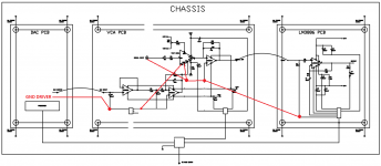
Have shown the existing earthing layout, where each pcb is mounted to the chassis plate there are copper tracks which run round the outside of the pcb and connect to the m4 mounting screws. On the amp pcb the individual earths are in star but the star connects both to the m4 mounting screws and to the main earth block on the chassis.
I have indicated where the copper tracks run between the mounting holes, not all corners are connected on the vca and the processor board.
Now I have drawn the earth schematic it does not look right even to me.
When I had the system working with the vca built on a breadboard the amp earthing was as shown but the vca earthing was with the double star and it worked fine so I thought the amp earthing was not causing the problem.
Attachments
It looks to me like you've created several ground loops. One that's system wide and run through the chassis and one on each board.
You may also want to rethink how the IV converter ground connects to the rest of the circuit.
Ya' know... If you can't turn an amp project into a power supply (or grounding) project, you're not doing it right...")
~Tom
You may also want to rethink how the IV converter ground connects to the rest of the circuit.
Ya' know... If you can't turn an amp project into a power supply (or grounding) project, you're not doing it right...
~Tom
the pdf is not legible.
At 300% I think I can read to main earth, but that is just little better than a guess.
I see a Signal Flow from VCA to 3886. You have no Signal Return.
You MUST run the Signal interconnect as a TWO wire Signal Flow and Return.
If you have repeated this type of error elsewhere, then these will add up to massive interference of the signal.
All connections MUST be TWO Wire. Outputs and Inputs and Power. Three wire for dual polarity Power.
I agree that the grounding scheme is non-ideal to say the least. As drawn, you'll have issues with ground loops, but I don't think it explains the issues the OP is having (see post #1).
With this grounding, you'll certainly get poor THD, but that's likely to be, say 0.1 % rather than 0.005 %. That's not something you'd necessarily pick out in a listening test or on an oscilloscope, but it would be easy to measure. But the poor grounding scheme shouldn't cause the signal to completely disappear in the way the OP is describing.
I think a bigger issue is that the signal ground to the I/V converter is taken from the digital ground. The LM3886 sits in its own little world. If you want the best performance, route the audio signals pseudo-differentially (as Andrew also points to). The best signal ground reference on the LM3886 board would be the ground connection at the output connector. You can convince yourself of this pretty easily by running a simulation of the impact of current in ground path from the load ground to the supply ground.
The best advice I can give is to simulate the ground scheme. Or at least draw out the ground resistances and look at where the high currents flow and how that impacts the low-level signals.
Also, sweep the THD vs frequency. I've found that a crappy grounding scheme will typically identify itself as a severe THD degradation at HF. You can see one of my experiments (with THD data) here: http://www.diyaudio.com/forums/chip-amps/252436-lm3886-pcb-vs-point-point-data-3.html#post3846783
~Tom
Will do another pdf, it came straight from acad.
Thanks for the info, not sure I quite understand everything yet.
Two wire signal system from vca to LM3886; can you explain a bit more as I do not know how the return wire should be connected.
Seems I have a lot of mods to do to get things right.
Thanks for the info, not sure I quite understand everything yet.
Two wire signal system from vca to LM3886; can you explain a bit more as I do not know how the return wire should be connected.
Seems I have a lot of mods to do to get things right.
- Status
- This old topic is closed. If you want to reopen this topic, contact a moderator using the "Report Post" button.
- Home
- Amplifiers
- Chip Amps
- VCA and LM3886 Mismatch