I wonder at what plate current and gm that composite will start oscillating though.")
How's the THD and noise on that composite? I kind of doubt it would be stable over the life of the tubes.
Mostly third harmonic at -75dB on 1mV pk-pk input and 32mV pk-pk output. Spice says so, don't know how pragmatic the model can be in the starved curves region. Noise, hmm I would not even bother modeling. Too many things the Spice will skip. Its you plan about 20mS gm and then each tube sample has own 1/F vices, you got a PSU to fight out, some layout critical stuff, the DMOS CCS current noise intrusion %. Should be happy to hit below 1.5nVrtHz I would guess. Such sensitive things are about test build, match, scope, FFT, tweak, and go at it again. Only then you know exactly. Frank says it was useable, so it should be worthy as tubes go.
Mostly third harmonic at -75dB on 1mV pk-pk input and 32mV pk-pk output. Spice says so, don't know how pragmatic the model can be in the starved curves region. Noise, hmm I would not even bother modeling. Too many things the Spice will skip. Its you plan about 20mS gm and then each tube sample has own 1/F vices, you got a PSU to fight out, some layout critical stuff, the DMOS CCS current noise intrusion %. Should be happy to hit below 1.5nVrtHz I would guess. Such sensitive things are about test build, match, scope, FFT, tweak, and go at it again. Only then you know exactly. Frank says it was useable, so it should be worthy as tubes go.
I'm surprised that it's mostly third harmonic. It should be mostly second.
Well, as far as noise is concerned, I just use the spice results as a guide.
How's the PSRR? It should be pretty good with the CCS load.
Such DMOS cascoded CCS can lend 120dB PSRR at ripple frequencies. But have some hiss to contribute on the other hand. Still when the input is single ended, some TT cable coupled hum will find its way in.
Yeah, I have that CCS at -100db up to about 200Hz in Tina spice, then gradually rising to -70dB at 20kHz.
If one was to go to differential inputs to cancel the hum pickup from the cable, then they would have the "problem" of killing off the second harmonic in the FFT, so it wouldn't sound as sweet. They can't use a transformer to convert balanced to single ended as far as I know because the reactive impedance of the MM cartridge is to high. It's no an easy situation.
Last edited:
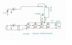
Looks like working, I set up a quick sim while we were posting. 1mV pk-pk input. Looks alright for output? R1 got to be a rheostat mode trimmer.
I think it would be more stable if each triode had it's own CCS. I don't know what that would do for the noise though.
Aren't you going to get grid current with this setup?
OK, I'm just curious and looking to learn new things. So, it looks like the input impedance would change a lot with the swing of the AC input voltage. It appears that on the positive half swing, the impedance would go way down, and then go back up again on the negative half swing. To me, that would be a recipe for really high distortion, and the distortion would be very much dependent on input level.
In general, I do not like to parallel any kind of active devices.
In general, I do not like to parallel any kind of active devices.
Depends on how much swing and at which positive point the grid really takes off. If its bad at +0.5V but passable at +0.1V then 0.25mV RMS LMC will only create 22.64mV pk-pk and it could be OK. Its the application it was made for that is very specific. Plus such a cart will have 5R-15R source impedance routinely. For high levels, obviously risky.
Depends on how much swing and at which positive point the grid really takes off. If its bad at +0.5V but passable at +0.1V then 0.25mV RMS LMC will only create 22.64mV pk-pk and it could be OK. Its the application it was made for that is very specific. Plus such a cart will have 5R-15R source impedance routinely. For high levels, obviously risky.
Oh, you're talking about a MC cartridge.
Still, not my cup of tea. Good luck with it, whoever uses it.
Hi,
Yes. It won't work with MM cartridges or any other type requiring MM type of termination (47K to 50K).
This circuit has a very low input impedance. Any loading higher than its input impedance will cause grid current to flow.
OTOH the MC loading values as recommended by the manufacturer are barely affected. E.g. a 100R load changes to say 97R which is still well into the ballpark.
Even though it's a SE circuit I never encountered any hum problems at all. Not ever. Never noticed any audible hiss either with the BF244A/245A as CCS which has an Idss of 2 to 6mA.
It does require very careful layout and good shielding from anything carrying AC.
I'll comment further later on today.
Ciao,
Oh, you're talking about a MC cartridge.
Yes. It won't work with MM cartridges or any other type requiring MM type of termination (47K to 50K).
This circuit has a very low input impedance. Any loading higher than its input impedance will cause grid current to flow.
OTOH the MC loading values as recommended by the manufacturer are barely affected. E.g. a 100R load changes to say 97R which is still well into the ballpark.
Even though it's a SE circuit I never encountered any hum problems at all. Not ever. Never noticed any audible hiss either with the BF244A/245A as CCS which has an Idss of 2 to 6mA.
It does require very careful layout and good shielding from anything carrying AC.
I'll comment further later on today.
Ciao,
Hi,
Yes. It won't work with MM cartridges or any other type requiring MM type of termination (47K to 50K).
This circuit has a very low input impedance. Any loading higher than its input impedance will cause grid current to flow.
OTOH the MC loading values as recommended by the manufacturer are barely affected. E.g. a 100R load changes to say 97R which is still well into the ballpark.
Even though it's a SE circuit I never encountered any hum problems at all. Not ever. Never noticed any audible hiss either with the BF244A/245A as CCS which has an Idss of 2 to 6mA.
It does require very careful layout and good shielding from anything carrying AC.
I'll comment further later on today.
Ciao,
There doesn't appear to be enough B+ to run a cascode Mosfet CCS. I'm measuring only about 1 VDC drop across it (about 22.6V on the plates @ 19.something mA).
Attachments
Hi,
Try lowering Rset to 60R or so. That should make the plate voltage drop to approximately 16Vdc which is roughly where you want it to be.
If the plate voltage is too high then the circuit's concept falls apart.
B+ is only limited by the output of the 7824 reg which, if must be, can be replaced by a low drop reg.
Ciao,
Hi,
Try lowering Rset to 60R or so. That should make the plate voltage drop to approximately 16Vdc which is roughly where you want it to be.
If the plate voltage is too high then the circuit's concept falls apart.
B+ is only limited by the output of the 7824 reg which, if must be, can be replaced by a low drop reg.
Ciao,
I was just trying to help out. I'm not interested enough in this to perfect it, sorry. I would use other techniques if I were to use a MC cartridge.
Hi,
No problem.
There's a high likelihood that the cascode ccs will need to be abandoned or reconfigured for lower current anyhow.
The reason being that the higher current is likely to increase the noise levels of the stage and that's of course the last thing we want to do.
Nonetheless it's worth to give it a try so we can at least have a "life" example that will show a relationship between Ia, gm and I/f for LF applications.
This is one of the many reasons this circuit was brought to the attention of the readers here.
Often people opt for high gm tubes with spectacular Req values (at UHF) based on the IME false premise that the 2.5/gm formula will wave its magic wand on their LF circuit.
While, and again this is only from personal experience, high gm valves certainly have their merit in retrieving fine detail, they also come with a set of cons. One of them is stability at LF which often requires counter measures which work against low noise anyway...
See also:
Tube Noise - Professional Vacuum Tube Audio
And also:
http://www.valvewizard.co.uk/Triodes_at_low_voltages_Blencowe.pdf
The latter link is extremely important to those who want to understand how this circuit came about.
If you read carefully through it the author (and I say it with the utmost respect) abandoned the exact topology this MC stage is based on because he saw no practical use for it.
Well, here you have it: the MC cartridge.
The rest of the design is, as has been pointed out, all about toeing the line of noise, stability and gain scaling.
Keeping in mind that it was a commissioned design dating somewhere around early 1987 isn't this interesting regardless of whether or not one likes or dislikes MC cartridges?
Ciao,
I was just trying to help out.
No problem.
There's a high likelihood that the cascode ccs will need to be abandoned or reconfigured for lower current anyhow.
The reason being that the higher current is likely to increase the noise levels of the stage and that's of course the last thing we want to do.
Nonetheless it's worth to give it a try so we can at least have a "life" example that will show a relationship between Ia, gm and I/f for LF applications.
This is one of the many reasons this circuit was brought to the attention of the readers here.
Often people opt for high gm tubes with spectacular Req values (at UHF) based on the IME false premise that the 2.5/gm formula will wave its magic wand on their LF circuit.
While, and again this is only from personal experience, high gm valves certainly have their merit in retrieving fine detail, they also come with a set of cons. One of them is stability at LF which often requires counter measures which work against low noise anyway...
See also:
Tube Noise - Professional Vacuum Tube Audio
And also:
http://www.valvewizard.co.uk/Triodes_at_low_voltages_Blencowe.pdf
The latter link is extremely important to those who want to understand how this circuit came about.
If you read carefully through it the author (and I say it with the utmost respect) abandoned the exact topology this MC stage is based on because he saw no practical use for it.
Well, here you have it: the MC cartridge.
The rest of the design is, as has been pointed out, all about toeing the line of noise, stability and gain scaling.
Keeping in mind that it was a commissioned design dating somewhere around early 1987 isn't this interesting regardless of whether or not one likes or dislikes MC cartridges?
Ciao,
I have a solution for this circuit, but it is not considered acceptable here. I won't say any more.
Yes, I'm well aware of 1/f noise being dominant at LF. That kind of noise is not predictable, but is dependent on specific manufacturing techniques and materials.
According to the first article, you should be operating those ECC88's at the lowest possible Ia for lowest 1/f noise. This is probably not where the tube is the most linear.
Last edited:
Hi,
How would you know if you do not propose it?
That is why using a CCS is so important here. That plus choosing the right kind of tube for the application. Datasheets and load line curves can tell a lot already.
Ciao,
I have a solution for this circuit, but it is not considered acceptable here. I won't say any more.
How would you know if you do not propose it?
This is probably not where the tube is the most linear.
That is why using a CCS is so important here. That plus choosing the right kind of tube for the application. Datasheets and load line curves can tell a lot already.
Ciao,
Last edited:
Im ponding on other tubes then 6SN7 as second follower for getting the output level up a bit from a 2,5 mV signal. Ideas, suggestions, nonos? E88CC, modern trioded pentodes, E280F, 6C45P...?
I'm sorry? you want a "second follower" to "get the output level up"???
Do you mean you want a second gain stage?
- Home
- Source & Line
- Analogue Source
- Valve Itch phono