R5 should be 10R if you will lift one pin and measure it. It should be ~9.45R on TP for 47//47R instead of trimmer. See about changing the Zeners, about surely having a Vout that allows at least 10V difference to Vin, and that also Q1 shows ~1-1.5V Vgs which you can also measure as Vds Q2 when you have the power on.
diff Vin-Vout 10V
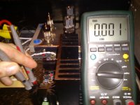
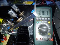
Q1 4.8V
Q2 0.9V
See you got 10V in-out for sure, then change Q1 too. Burned Zeners you found show that something went wrong at a point sometime.
I suspected the same, I will change Q1.
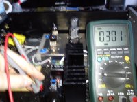
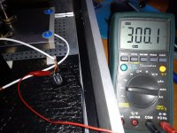
But you got an operating led. 1mV through 10 Ohm TP means 0.1mA. How it can operate the Vref's CCS to set 300V and light the LED? Fishy measurement. Is the sink getting warm?
Both heatsinks cold
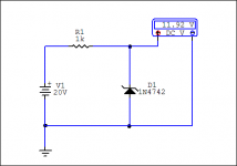
To properly test a Zener we need a higher DC voltage source than its value, a protective resistor, then we measure if it meets its value. A little circuit in other words.
I would dummy up the reg load, wet the TP pads with some solder to be sure they conduct to the probes well at all times, and test it in isolation to the Itch for components, oscillation with the scope, different power source or grounding, such stuff. All those data up to now are contradictory. Once it conducts showing well on TP but does not trim CCS there is a bricked trimmer, then it shows 0.1mA but its Vref and led works and 300V voltage is set that needs over 2mA to work in itself and there is some warmth even, then some zeners seem burned but not sure, then some DN2540 changed but not sure of their condition etc. Still there was never smoke. Can't draw a conclusion. DN2540 are like JFETs and can be tested for IDSS by the way, expecting rough 150mA range. You did well to get some even for spares if those you already got will prove good. They are very useful with tubes in general. So gather some certain experimental data, and if there is a defect in parts it will stand out with exchanging. How it played music without ripple hum and sets to an output voltage its perplexing nonetheless. I would also try a different C1. I hope it isn't like the other one you had once that its belly was conductive to the extra pads.
I would dummy up the reg load, wet the TP pads with some solder to be sure they conduct to the probes well at all times, and test it in isolation to the Itch for components, oscillation with the scope, different power source or grounding, such stuff. All those data up to now are contradictory. Once it conducts showing well on TP but does not trim CCS there is a bricked trimmer, then it shows 0.1mA but its Vref and led works and 300V voltage is set that needs over 2mA to work in itself and there is some warmth even, then some zeners seem burned but not sure, then some DN2540 changed but not sure of their condition etc. Still there was never smoke. Can't draw a conclusion. DN2540 are like JFETs and can be tested for IDSS by the way, expecting rough 150mA range. You did well to get some even for spares if those you already got will prove good. They are very useful with tubes in general. So gather some certain experimental data, and if there is a defect in parts it will stand out with exchanging. How it played music without ripple hum and sets to an output voltage its perplexing nonetheless. I would also try a different C1. I hope it isn't like the other one you had once that its belly was conductive to the extra pads.
Attachments
")
Followed in Power supplies forum Simplistic Mosfet HV shunt regulator
http://www.diyaudio.com/forums/power-supplies/134801-simplistic-mosfet-hv-shunt-regs-348.html
http://www.diyaudio.com/forums/power-supplies/134801-simplistic-mosfet-hv-shunt-regs-348.html
- Home
- Source & Line
- Analogue Source
- Valve Itch phono