Listened to those, the Itch one certainly reflects a strong hf response problem, the MF one is no par to some Fran's files. You have a bright future and a dim present in other words. Go to slow debugging checks for connections, voltages, and values, the mistake or problem sounds common to both channels. Additionally take and post some photos of everything as connected now, in case we can spot something and be of help.
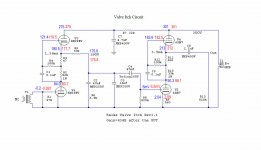
The bias voltages look OK in most places except than input DC, is that ~0.2V? And upper tubes voltages between grid and cathode. They look way much wide. Don't know if Fran can check in his to see if those points follow for a confirmation. Do you use an input transformer?
*There are possible explanations but its early to guess. Confirm R4, R5, R12, C3 values meanwhile if you can.
*There are possible explanations but its early to guess. Confirm R4, R5, R12, C3 values meanwhile if you can.
Aha! Big improvement.
I've got a pretty bad buzz now, but I think that's because the chassis isn't grounded and is laying on its side. I imagine once I ground it and button it up properly that will go away.
I feel like the V-LPS is clearer in the upper range, but that might have something to do with the buzz on the Itch recording (which wasn't there when I recorded the V-LPS file).
Attachments
Don't consider listening VS something seriously yet. The test shows the build has problems of excessive input DC that polarizes the cart and maybe other stuff too. The HF did not come full anyway. Let Fran see if the voltages are following maybe, but check everything is according to plans meanwhile, especially confirm those parts values I mentioned above. Are those tubes -ev?
I thought they were, but it appears that they are not.Are those tubes -ev?
I've begun having a constant static type of noise. It wasn't there before but now it won't go away. I tried swapping all of my tubes, but they're all tubes from the same batch.
Is it possible I was sold a batch of bad tubes?
Don't know, maybe. Spend time to encase and ground the construction properly meantime, its high gain-low signal so it needs some be-together standards, show us pictures after that. That way it will be steady, we could look into wiring, tube types, maybe Fran can spot check a couple of crucial voltage parameters in his build to see if they track, and we will give a hand to debug it. They all succeed in the end.
I'd say go over every connection and component. It can't hurt and you might get lucky. I had a fair bit of debugging on mine to get it absolutely quiet, but then it was quiet.
A few pics would help us to help you too, maybe go back through this thread and look at my pics and it might help jog something? You'll see I had issues!!
I can't get to check mine tonight, but I'll open it up tomorrow night and check voltages. I have mine wired with either direct input for MM or through a step up for MC. I'm using MM at the moment as my MC just went for a retip - so I'm using mine exactly as you are.
Fran
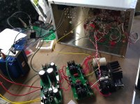
I just got it all grounded and put together. When I turned it on, something went POP. I'm letting it sit for a while before I open it back up.
I might have to rethink how I'm doing this and go back a few steps. Maybe I should use 2 chassis so I can have plenty of space to spread out this circuit.
I attached a few pictures from the build process.
I might have to rethink how I'm doing this and go back a few steps. Maybe I should use 2 chassis so I can have plenty of space to spread out this circuit.
I attached a few pictures from the build process.
Attachments
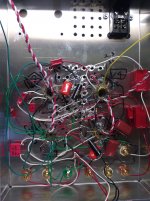
Something I find helpful - maybe you have done this already. I print out the sch and go through each and every connection, and tick them off on paper one by one to make sure its ok. One colour pen for left and another for right.
You build like me - its a bit messy - so its kinda hard to easily find something missing afterwards. The sch and pen has been my friend on many occasions!!
I hope to get a chance tomorrow night to take measurements for you.
Fran
You build like me - its a bit messy - so its kinda hard to easily find something missing afterwards. The sch and pen has been my friend on many occasions!!
I hope to get a chance tomorrow night to take measurements for you.
Fran
That's actually exactly what I do. I use a highlighter and highlight each connection after I verify that it's there. It won't hurt to go back over it, though.Something I find helpful - maybe you have done this already. I print out the sch and go through each and every connection, and tick them off on paper one by one to make sure its ok.
I think I figured out what happened. The leads from Q1 on the SSHV board weren't clipped short enough, so they made contact with the bottom plate of the chassis. When I turned it on... pop. Nothing looks burned, but 345 V are going into the SSHV and only 6.4 are coming out. I'm pretty sure I burned up Q1.
I'll try to pull it off the board tomorrow and replace it. Unsoldering a 3-pin package like that is so hard. If anyone has any tips I'd be glad to hear them.
If there is weird reading on TP points then Q1 (CCS cascoding Mosfet) could have gone. But if there is normal reading there, it could had hit something further down. So check first. Use wick and/or desoldering pump. Some flux would help the wick if you got any in liquid form or paste.
<snip>
I'll try to pull it off the board tomorrow and replace it. Unsoldering a 3-pin package like that is so hard. If anyone has any tips I'd be glad to hear them.
A dentist would break it up into pieces and pull each root separately. I have cut the legs off op-amps, you cannot get them all hot at once without hot air. Once each leg is hot you can push it through with a tooth pick.
DT
So I checked your voltages against mine and all yours check out AOK except:
grid of V1 - I get ~1-3mVDC there
grid of V2 - I get absolutely flat 0VDC
My B+ is a little lower than yours, about 275-280V out of the shunt, so all my voltages are a little lower than yours, but the proportion is exactly the same.
I think you need to look at the voltage on the input grid in particular, then after that the layout.
Fran
- Home
- Source & Line
- Analogue Source
- Valve Itch phono