Probably a daft question - If one has a model of a pentode. and it is triode wired, is the performance of the tube still model-able if the connection is made explicitly in LTSpice, from g2 to anode? I suppose I am trying to understand the rationale for seperate models for triode-connected pentodes.
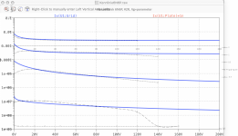
I derived a triode model for EF12 using Dmitry Nizhegorodov's curve mapping tool. I could only manage a close match, after spending a long time on finding a correlation. I like this empirical approach to validating designs, and I am interested in how people build confidence in the models they are using.
I derived a triode model for EF12 using Dmitry Nizhegorodov's curve mapping tool. I could only manage a close match, after spending a long time on finding a correlation. I like this empirical approach to validating designs, and I am interested in how people build confidence in the models they are using.
if your pentode model delivers correct results for ANY Vg2, you don't need an extra triode-connected model.
Hi Adrian, How do I confirm that the model incorporates Vg2? Should I try to emulate curves where Vg2 is changed, and look for a correlation?
Cheers, Richard
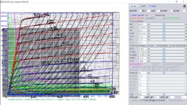
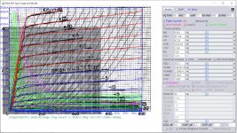
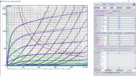
Here is 807/1625 RCA model, 807 heater is 6.3V, 1625 is 12.6V and pin-out is different. Also attached is Extract V3.000 1625 model but the positive range is somewhat out. These models are similar to 6L6 but more extended Vg1 range.
Code:
 *** 807 ************************************G4******
* Created on 02/09/2021 22:16 using paint_kip.jar
* [URL="http://www.dmitrynizh.com/tubeparams_image.htm"]www.dmitrynizh.com/tubeparams_image.htm[/URL]
* Plate Curves image file: 807.png
* Data source link: <plate curves URL>
*----------------------------------------------------------------------------------
.SUBCKT 807 P G2 G K ; LTSpice tetrode.asy pinout
* .SUBCKT 807 P G K G2 ; Koren Pentode Pspice pinout
+ PARAMS: MU=8.952 KG1=1178.02 KP=42.4 KVB=1811.65 VCT=-2.18 EX=1.277 KG2=1106.5 KNEE=8.776 KVC=1.809
+ KLAM=3.125E-9 KLAMG=2.935E-4  KD=45.73 KC=10.12 KR1=0.001196 KR2=0.0256 KVBG=0.024 KB1=5.6 KB2=2.12 KB3=1.24 KB4=0.285 KVBGI=6.104E-9 KNK=0.27 KNG=0.02253 KNPL=0.007808 KNSL=0.00325 KNPR=0.379 KNSR=29.18
+ CCG=12P CGP=0.2P CCP=7P VGOFF=-2.25 IGA=0.003648 IGB=0.039 IGC=0.1 IGEX=1.88
* Vp_MAX=800 Ip_MAX=500 Vg_step=5 Vg_start=30 Vg_count=17
* X_MIN=53 Y_MIN=66 X_SIZE=717 Y_SIZE=561 FSZ_X=1296 FSZ_Y=736 XYGrid=true
* Rp=1400 Vg_ac=20 P_max=25 Vg_qui=-10 Vp_qui=300
* showLoadLine=n showIp=y isDHP=n isPP=n isAsymPP=n isUL=n showDissipLimit=y
* showIg1=y isInputSnapped=y addLocalNFB=n
* XYProjections=n harmonicPlot=y dissipPlot=n
* UL=0.43 EG2=250 gridLevel2=y addKink=y isTanhKnee=n advSigmoid=y
*----------------------------------------------------------------------------------
RE1  7 0  1G    ; DUMMY SO NODE 7 HAS 2 CONNECTIONS
E1   7 0  VALUE=  ; E1 BREAKS UP LONG EQUATION FOR G1.
+{V(G2,K)/KP*LOG(1+EXP((1/MU+(VCT+V(G,K))/SQRT(KVB+V(G2,K)*V(G2,K)))*KP))}
RE2  6 0  1G    ; DUMMY SO NODE 6 HAS 2 CONNECTIONS
E2  6 0  VALUE={(PWR(V(7),EX)+PWRS(V(7),EX))} ; Kg1 times KIT current
E4   8 0  VALUE={V(P,K)/KNEE/(KVBGI+V(6)*KVBG)}
E5  81 0  VALUE={PWR(V(8),KB1)}
E6  82 0  VALUE={PWR(V(8),KB2)}
E7  83 0  VALUE={PWR(V(8),KB3)}
E8   9 0  VALUE={PWR(1-EXP(-V(81)*(KC+KR1*V(82))/(KD+KR2*V(83))),KB4)*1.5708}
RE4  8 0  1
RE5 81 0  1
RE6 82 0  1
RE7 83 0  1
RE8  9 0  1
RE21 21 0 1
E21  21 0 VALUE={V(6)/KG1*V(9)} ; Ip with knee but no slope and no kink
RE22 22 0 1 ; E22: kink curr deviation for plate
E22  22 0 VALUE={V(21)*LIMIT(KNK-V(G,K)*KNG,0,0.3)*(-ATAN((V(P,K)-KNPL)/KNSL)+ATAN((V(P,K)-KNPR)/KNSR))}
G1   P K  VALUE={V(21)*(1+KLAMG*V(P,K))+KLAM*V(P,K) + V(22)}
G2   G2 K  VALUE={V(6)/KG2*(KVC-V(9))/(1+KLAMG*V(P,K)) - V(22)}
RCP  P K  1G     ; FOR CONVERGENCE
C1   K G  {CCG}  ; CATHODE-GRID 1
C2   G P  {CGP}  ; GRID 1-PLATE
C3   K P  {CCP}  ; CATHODE-PLATE
RE23 G 0 1G
GG G K VALUE={(IGA+IGB/(IGC+V(P,K)))*(MU/KG1)*
+(PWR(V(G,K)-VGOFF,IGEX)+PWRS(V(G,K)-VGOFF,IGEX))}
.ENDS
*$
Code:
****************************************************
.SUBCKT 1625 1 2 3 4 ; A G2 G1 C;
* Extract V3.000 * Model created: 29-Apr-2020 *
X1 1 2 3 4 BTetrodeDE MU= 9.64 EX=1.372 kG1= 519.7 KP= 42.1 kVB = 4096.6 kG2= 7370.3
+Sc=.26E-01 ap= .018 w= 20. nu= 3.12 lam= 6.2
+ Ookg1mOokG2=.179E-02 Aokg1=.11E-05 alkg1palskg2=.179E-02 be= .057 als= 6.85 RGI=2000
+ CCG1=11P CCG2 = 0.0p CPG1 = 0.2p CG1G2 = 0.0p CCP=7P ;
.ENDS
****************************************************
.SUBCKT BTetrodeDE 1 2 3 4; A G2 G1 C
* * NOTE: LOG(x) is base e LOG or natural logarithm.
* For some Spice versions, e.g. MicroCap, this has to be changed to LN(x).
*
RE1 7 0 1MEG ; DUMMY SO NODE 7 HAS 2 CONNECTIONS
E1 7 0 VALUE=
+{V(2,4)/KP*LOG(1+EXP(KP*(1/MU+V(3,4)/SQRT(KVB+V(2,4)*V(2,4)))))}
E2 8 0 VALUE = {Ookg1mOokG2 + Aokg1*V(1,4) - alkg1palskg2*Exp(-be*V(1,4)*SQRT(be*V(1,4)))}
E3 9 0 VALUE = {Sc/kG2*V(1,4)*(1+tanh(-ap*(V(1,4)-V(2,4)/lam+w+nu*V(3,4))))}
G1 1 4 VALUE = {0.5*(PWR(V(7),EX)+PWRS(V(7),EX))*(V(8)-V(9))}
G2 2 4 VALUE = {0.5*(PWR(V(7),EX)+PWRS(V(7),EX))/KG2 *(1+als*Exp(-be*V(1,4) * SQRT(be*V(1,4))))}
RCP 1 4 1G ; FOR CONVERGENCE A - C
C1 3 4 {CCG1} ; CATHODE-GRID 1 C - G1
C4 2 4 {CCG2} ; CATHODE-GRID 2 C - G2
C5 2 3 {CG1G2} ; GRID 1 -GRID 2 G1 - G2
C2 1 3 {CPG1} ; GRID 1-PLATE G1 - A
C3 1 4 {CCP} ; CATHODE-PLATE A - C
R1 3 5 {RGI} ; FOR GRID CURRENT G1 - 5
D3 5 4 DX ; FOR GRID CURRENT 5 - C
.MODEL DX D(IS=1N RS=1 CJO=10PF TT=1N)
.ENDS BTetrodeDE
Attachments
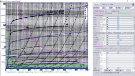
This 807 model is more robust than the previous model as it can be ran in more schematics. I disable some of the options like making KB1, KB3 =0 in Advance Knee Params. The makes the model less complex and easier to be handled by Spice software. Also I recommend using the following option in LTSpice:
.options GminSteps=0
.options NoOpIter
.options SrcSteps=380000
This will make the source steps very small and allow Spice to have sufficient step to complete simulation without premature quitting. It'll take a little longer but it will be completed.
.options GminSteps=0
.options NoOpIter
.options SrcSteps=380000
This will make the source steps very small and allow Spice to have sufficient step to complete simulation without premature quitting. It'll take a little longer but it will be completed.
Code:
**** 807 ******************************************
* Created on 02/10/2021 17:34 using paint_kip.jar
* [URL="http://www.dmitrynizh.com/tubeparams_image.htm"]Model Paint Tools: Trace Tube Parameters over Plate Curves, Interactively[/URL]
* Plate Curves image file: 807.png
* Data source link: <plate curves URL>
*----------------------------------------------------------------------------------
.SUBCKT 807 P G2 G K ; LTSpice tetrode.asy pinout
* .SUBCKT 807 P G K G2 ; Koren Pentode Pspice pinout
+ PARAMS: MU=8.952 KG1=471.94 KP=42.36 KVB=1630.48 VCT=-7.89 EX=1.08 KG2=353.2 KNEE=0.3401 KVC=1.809
+ KLAM=3.047E-10 KLAMG=2.398E-4  KD=1211.72 KC=359999.82 KR1=0.1866 KR2=4.125E6 KVBG=4.259E-5 KB1=0 KB2=1.681 KB3=0 KB4=2.433 KVBGI=5.341E-7 KNK=0.06215 KNG=0.004617 KNPL=0.001662 KNSL=0.7774 KNPR=56.92 KNSR=44.23
+ CCG=12P CGP=0.2P CCP=7P VGOFF=-2.25 IGA=0.001788 IGB=0.039 IGC=0.1 IGEX=1.88
* Vp_MAX=800 Ip_MAX=500 Vg_step=5 Vg_start=30 Vg_count=17
* X_MIN=48 Y_MIN=10 X_SIZE=717 Y_SIZE=561 FSZ_X=1288 FSZ_Y=723 XYGrid=true
* Rp=1400 Vg_ac=20 P_max=25 Vg_qui=-10 Vp_qui=300
* showLoadLine=n showIp=y isDHP=n isPP=n isAsymPP=n isUL=n showDissipLimit=y
* showIg1=y isInputSnapped=y addLocalNFB=n
* XYProjections=n harmonicPlot=y dissipPlot=n
* UL=0.43 EG2=250 gridLevel2=y addKink=y isTanhKnee=n advSigmoid=y
*----------------------------------------------------------------------------------
RE1  7 0  1G    ; DUMMY SO NODE 7 HAS 2 CONNECTIONS
E1   7 0  VALUE=  ; E1 BREAKS UP LONG EQUATION FOR G1.
+{V(G2,K)/KP*LOG(1+EXP((1/MU+(VCT+V(G,K))/SQRT(KVB+V(G2,K)*V(G2,K)))*KP))}
RE2  6 0  1G    ; DUMMY SO NODE 6 HAS 2 CONNECTIONS
E2  6 0  VALUE={(PWR(V(7),EX)+PWRS(V(7),EX))} ; Kg1 times KIT current
E4   8 0  VALUE={V(P,K)/KNEE/(KVBGI+V(6)*KVBG)}
E5  81 0  VALUE={PWR(V(8),KB1)}
E6  82 0  VALUE={PWR(V(8),KB2)}
E7  83 0  VALUE={PWR(V(8),KB3)}
E8   9 0  VALUE={PWR(1-EXP(-V(81)*(KC+KR1*V(82))/(KD+KR2*V(83))),KB4)*1.5708}
RE4  8 0  1
RE5 81 0  1
RE6 82 0  1
RE7 83 0  1
RE8  9 0  1
RE21 21 0 1
E21  21 0 VALUE={V(6)/KG1*V(9)} ; Ip with knee but no slope and no kink
RE22 22 0 1 ; E22: kink curr deviation for plate
E22  22 0 VALUE={V(21)*LIMIT(KNK-V(G,K)*KNG,0,0.3)*(-ATAN((V(P,K)-KNPL)/KNSL)+ATAN((V(P,K)-KNPR)/KNSR))}
G1   P K  VALUE={V(21)*(1+KLAMG*V(P,K))+KLAM*V(P,K) + V(22)}
G2   G2 K  VALUE={V(6)/KG2*(KVC-V(9))/(1+KLAMG*V(P,K)) - V(22)}
RCP  P K  1G     ; FOR CONVERGENCE
C1   K G  {CCG}  ; CATHODE-GRID 1
C2   G P  {CGP}  ; GRID 1-PLATE
C3   K P  {CCP}  ; CATHODE-PLATE
RE23 G 0 1G
GG G K VALUE={(IGA+IGB/(IGC+V(P,K)))*(MU/KG1)*
+(PWR(V(G,K)-VGOFF,IGEX)+PWRS(V(G,K)-VGOFF,IGEX))}
.ENDS
*$
Attachments
Last edited:
This is Mullard EL34 model, the curve is smooth so no Knee/Slope or Advance Knee/Slope is used, so no Option is required and it runs faster in simulation.
Code:
*** EL34_MU-2 ******************************6************
* Created on 02/11/2021 13:57 using paint_kip.jar
* [URL="http://www.dmitrynizh.com/tubeparams_image.htm"]Model Paint Tools: Trace Tube Parameters over Plate Curves, Interactively[/URL]
* Plate Curves image file: el34-mu.png
* Data source link: <plate curves URL>
*----------------------------------------------------------------------------------
.SUBCKT EL34 P G2 G K ; LTSpice tetrode.asy pinout
* .SUBCKT EL34 P G K G2 ; Koren Pentode Pspice pinout
+ PARAMS: MU=12.04 KG1=1305.54 KP=62.44 KVB=5480.79 VCT=1.73 EX=1.494 KG2=1134.84 KNEE=14.78 KVC=1.799
+ KLAM=2E-6 KLAMG=5.51E-4   KNK=5.296E-4 KNG=0.01341 KNPL=0.2079 KNSL=90.05 KNPR=67.88 KNSR=27.4
+ CCG=3P CGP=1.4P CCP=1.9P VGOFF=-1.5 IGA=7.283E-4 IGB=0.237 IGC=7.12 IGEX=1.6
* Vp_MAX=500 Ip_MAX=350 Vg_step=5 Vg_start=0 Vg_count=8
* X_MIN=64 Y_MIN=28 X_SIZE=758 Y_SIZE=570 FSZ_X=1296 FSZ_Y=736 XYGrid=false
* Rp=1400 Vg_ac=20 P_max=25 Vg_qui=-17.5 Vp_qui=300
* showLoadLine=n showIp=y isDHP=n isPP=n isAsymPP=n isUL=n showDissipLimit=y
* showIg1=y isInputSnapped=y addLocalNFB=n
* XYProjections=n harmonicPlot=y dissipPlot=n
* UL=0.43 EG2=250 gridLevel2=y addKink=y isTanhKnee=n advSigmoid=n
*----------------------------------------------------------------------------------
RE1  7 0  1G    ; DUMMY SO NODE 7 HAS 2 CONNECTIONS
E1   7 0  VALUE=  ; E1 BREAKS UP LONG EQUATION FOR G1.
+{V(G2,K)/KP*LOG(1+EXP((1/MU+(VCT+V(G,K))/SQRT(KVB+V(G2,K)*V(G2,K)))*KP))}
RE2  6 0  1G    ; DUMMY SO NODE 6 HAS 2 CONNECTIONS
E2  6 0  VALUE={(PWR(V(7),EX)+PWRS(V(7),EX))} ; Kg1 times KIT current
RE21 21 0 1
E21  21 0 VALUE={V(6)/KG1*ATAN(V(P,K)/KNEE)} ; Ip with knee but no slope and no kink
RE22 22 0 1 ; E22: kink curr deviation for plate
E22  22 0 VALUE={V(21)*LIMIT(KNK-V(G,K)*KNG,0,0.3)*(-ATAN((V(P,K)-KNPL)/KNSL)+ATAN((V(P,K)-KNPR)/KNSR))}
G1   P  K  VALUE={V(21)*(1+KLAMG*V(P,K))+KLAM*V(P,K) + V(22)}
* Alexander Gurskii screen current, see audioXpress 2/2011, with slope and kink added
RE43 43 K 1G ; Dummy
E43  43 G2 VALUE={0} ; Dummy
G2   43 K  VALUE={V(6)/KG2*(KVC-ATAN(V(P,K)/KNEE))/(1+KLAMG*V(P,K))-V(22)}
RCP  P K  1G     ; FOR CONVERGENCE
C1   K G  {CCG}  ; CATHODE-GRID 1
C2   G P  {CGP}  ; GRID 1-PLATE
C3   K P  {CCP}  ; CATHODE-PLATE
RE23 G 0 1G
GG G K VALUE={(IGA+IGB/(IGC+V(P,K)))*(MU/KG1)*
+(PWR(V(G,K)-VGOFF,IGEX)+PWRS(V(G,K)-VGOFF,IGEX))}
.ENDS
*$
Attachments
Last edited:
This is 6L6GC RCA model being made less complex by setting Knee/Slope KB1 and KB3 to 0.
It works with the following options:
.options GminSteps=0
.options NoOpIter
.options SrcSteps=20
It works with the following options:
.options GminSteps=0
.options NoOpIter
.options SrcSteps=20
Code:
**** 6L6GC_RCA *************************L6*****************
* Created on 02/12/2021 01:44 using paint_kip.jar
* [url=http://www.dmitrynizh.com/tubeparams_image.htm]Model Paint Tools: Trace Tube Parameters over Plate Curves, Interactively[/url]
* Plate Curves image file: 6L6GC-RCA.png
* Data source link: <plate curves URL>
*----------------------------------------------------------------------------------
.SUBCKT 6L6GC P G2 G K ; LTSpice tetrode.asy pinout
* .SUBCKT 6L6GC P G K G2 ; Koren Pentode Pspice pinout
+ PARAMS: MU=9.37 KG1=1057.35 KP=43.88 KVB=21148.73 VCT=-6.207 EX=1.311 KG2=1521.16 KNEE=0.05078 KVC=1.759
+ KLAM=7.263E-8 KLAMG=4.379E-4  KD=2.28E8 KC=9765.62 KR1=1.808 KR2=0.06272 KVBG=6.026E-4 KB1=0 KB2=2.23 KB3=0 KB4=1.384 KVBGI=0.03725 KNK=0.03138 KNG=0.00513 KNPL=4.198E-10 KNSL=15.93 KNPR=53.36 KNSR=65.29
+ CCG=10P CGP=0.6P CCP=6.5P VGOFF=-1.5 IGA=0.001 IGB=0.3 IGC=8 IGEX=1.54
* Vp_MAX=700 Ip_MAX=300 Vg_step=10 Vg_start=0 Vg_count=8
* X_MIN=55 Y_MIN=1 X_SIZE=778 Y_SIZE=627 FSZ_X=1296 FSZ_Y=736 XYGrid=true
* Rp=1400 Vg_ac=20 P_max=30 Vg_qui=-35 Vp_qui=300
* showLoadLine=n showIp=y isDHP=n isPP=n isAsymPP=n isUL=n showDissipLimit=y
* showIg1=y isInputSnapped=y addLocalNFB=n
* XYProjections=n harmonicPlot=y dissipPlot=n
* UL=0.43 EG2=300 gridLevel2=y addKink=y isTanhKnee=n advSigmoid=y
*----------------------------------------------------------------------------------
RE1  7 0  1G    ; DUMMY SO NODE 7 HAS 2 CONNECTIONS
E1   7 0  VALUE=  ; E1 BREAKS UP LONG EQUATION FOR G1.
+{V(G2,K)/KP*LOG(1+EXP((1/MU+(VCT+V(G,K))/SQRT(KVB+V(G2,K)*V(G2,K)))*KP))}
RE2  6 0  1G    ; DUMMY SO NODE 6 HAS 2 CONNECTIONS
E2  6 0  VALUE={(PWR(V(7),EX)+PWRS(V(7),EX))} ; Kg1 times KIT current
E4   8 0  VALUE={V(P,K)/KNEE/(KVBGI+V(6)*KVBG)}
E5  81 0  VALUE={PWR(V(8),KB1)}
E6  82 0  VALUE={PWR(V(8),KB2)}
E7  83 0  VALUE={PWR(V(8),KB3)}
E8   9 0  VALUE={PWR(1-EXP(-V(81)*(KC+KR1*V(82))/(KD+KR2*V(83))),KB4)*1.5708}
RE4  8 0  1
RE5 81 0  1
RE6 82 0  1
RE7 83 0  1
RE8  9 0  1
RE21 21 0 1
E21  21 0 VALUE={V(6)/KG1*V(9)} ; Ip with knee but no slope and no kink
RE22 22 0 1 ; E22: kink curr deviation for plate
E22  22 0 VALUE={V(21)*LIMIT(KNK-V(G,K)*KNG,0,0.3)*(-ATAN((V(P,K)-KNPL)/KNSL)+ATAN((V(P,K)-KNPR)/KNSR))}
G1   P K  VALUE={V(21)*(1+KLAMG*V(P,K))+KLAM*V(P,K) + V(22)}
G2   G2 K  VALUE={V(6)/KG2*(KVC-V(9))/(1+KLAMG*V(P,K)) - V(22)}
RCP  P K  1G     ; FOR CONVERGENCE
C1   K G  {CCG}  ; CATHODE-GRID 1
C2   G P  {CGP}  ; GRID 1-PLATE
C3   K P  {CCP}  ; CATHODE-PLATE
RE23 G 0 1G
GG G K VALUE={(IGA+IGB/(IGC+V(P,K)))*(MU/KG1)*
+(PWR(V(G,K)-VGOFF,IGEX)+PWRS(V(G,K)-VGOFF,IGEX))}
.ENDS
*$
Attachments
Refer to Vacuum Tube SPICE Models
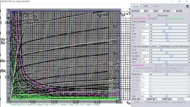
This PL519 Philips has been remodeled again, it runs with following options:
.options GminSteps=0
.options NoOpIter
.options SrcSteps=20
This PL519 Philips has been remodeled again, it runs with following options:
.options GminSteps=0
.options NoOpIter
.options SrcSteps=20
Code:
**** PL519_P ************************L1-3******************
* Created on 02/13/2021 20:13 using paint_kip.jar
* [url=http://www.dmitrynizh.com/tubeparams_image.htm]Model Paint Tools: Trace Tube Parameters over Plate Curves, Interactively[/url]
* Plate Curves image file: pl519_p.png
* Data source link: <plate curves URL>
*----------------------------------------------------------------------------------
.SUBCKT PL519 P G2 G K ; LTSpice tetrode.asy pinout
* .SUBCKT PL519 P G K G2 ; Koren Pentode Pspice pinout
+ PARAMS: MU=3.486 KG1=26089.53 KP=22.1 KVB=0 VCT=7.685 EX=2.3 KG2=34084.71 KNEE=6.86 KVC=1.644
+ KLAMG=5.702E-4  KD=0.02666 KC=9.92 KR1=0.001573 KR2=0.1656 KVBG=0.005306 KB1=1.027 KB2=1 KB3=0.0756 KB4=2.387 KVBGI=11.84 KNK=7.629E-7 KNG=0.002511 KNPL=8.043E-4 KNSL=8.257 KNPR=181.28 KNSR=55.94
+ CCG=0.2P CGP=3P CCP=1P VGOFF=-1 IGA=0.001 IGB=0.3 IGC=7.44 IGEX=1.3
* Vp_MAX=500 Ip_MAX=2000 Vg_step=10 Vg_start=0 Vg_count=22
* X_MIN=68 Y_MIN=51 X_SIZE=736 Y_SIZE=598 FSZ_X=1296 FSZ_Y=736 XYGrid=false
* Rp=1400 Vg_ac=20 P_max=45 Vg_qui=-105 Vp_qui=300
* showLoadLine=n showIp=y isDHP=n isPP=n isAsymPP=n isUL=n showDissipLimit=y
* showIg1=y isInputSnapped=y addLocalNFB=n
* XYProjections=n harmonicPlot=y dissipPlot=n
* UL=0.43 EG2=190 gridLevel2=y addKink=y isTanhKnee=n advSigmoid=y
*----------------------------------------------------------------------------------
RE1  7 0  1G    ; DUMMY SO NODE 7 HAS 2 CONNECTIONS
E1   7 0  VALUE=  ; E1 BREAKS UP LONG EQUATION FOR G1.
+{V(G2,K)/KP*LOG(1+EXP((1/MU+(VCT+V(G,K))/SQRT(KVB+V(G2,K)*V(G2,K)))*KP))}
RE2  6 0  1G    ; DUMMY SO NODE 6 HAS 2 CONNECTIONS
E2  6 0  VALUE={(PWR(V(7),EX)+PWRS(V(7),EX))} ; Kg1 times KIT current
E4   8 0  VALUE={V(P,K)/KNEE/(KVBGI+V(6)*KVBG)}
E5  81 0  VALUE={PWR(V(8),KB1)}
E6  82 0  VALUE={PWR(V(8),KB2)}
E7  83 0  VALUE={PWR(V(8),KB3)}
E8   9 0  VALUE={PWR(1-EXP(-V(81)*(KC+KR1*V(82))/(KD+KR2*V(83))),KB4)*1.5708}
RE4  8 0  1
RE5 81 0  1
RE6 82 0  1
RE7 83 0  1
RE8  9 0  1
RE21 21 0 1
E21  21 0 VALUE={V(6)/KG1*V(9)} ; Ip with knee but no slope and no kink
RE22 22 0 1 ; E22: kink curr deviation for plate
E22  22 0 VALUE={V(21)*LIMIT(KNK-V(G,K)*KNG,0,0.3)*(-ATAN((V(P,K)-KNPL)/KNSL)+ATAN((V(P,K)-KNPR)/KNSR))}
G1   P K  VALUE={V(21)*(1+KLAMG*V(P,K)) + V(22)}
G2   G2 K  VALUE={V(6)/KG2*(KVC-V(9))/(1+KLAMG*V(P,K)) - V(22)}
RCP  P K  1G     ; FOR CONVERGENCE
C1   K G  {CCG}  ; CATHODE-GRID 1
C2   G P  {CGP}  ; GRID 1-PLATE
C3   K P  {CCP}  ; CATHODE-PLATE
RE23 G 0 1G
GG G K VALUE={(IGA+IGB/(IGC+V(P,K)))*(MU/KG1)*
+(PWR(V(G,K)-VGOFF,IGEX)+PWRS(V(G,K)-VGOFF,IGEX))}
.ENDS
*$
Attachments
This EL509 JJ model, it runs with the following options:
.options GminSteps=0
.options NoOpIter
.options SrcSteps=20
.options GminSteps=0
.options NoOpIter
.options SrcSteps=20
Code:
**** EL509_JJ ************************L1-2******************
* Created on 02/13/2021 17:55 using paint_kip.jar
* [url=http://www.dmitrynizh.com/tubeparams_image.htm]Model Paint Tools: Trace Tube Parameters over Plate Curves, Interactively[/url]
* Plate Curves image file: el509_jj.png
* Data source link: <plate curves URL>
*----------------------------------------------------------------------------------
.SUBCKT EL509 P G2 G K ; LTSpice tetrode.asy pinout
* .SUBCKT EL509 P G K G2 ; Koren Pentode Pspice pinout
+ PARAMS: MU=3.591 KG1=3431.47 KP=27.42 KVB=131.34 VCT=4.523 EX=1.874 KG2=5324.45 KNEE=2.478 KVC=1.587
+ KLAM=2.57E-13 KLAMG=4.199E-4 KNEE2=27.32 KNEX=0.596  KNK=0.02886 KNG=0.01649 KNPL=20.67 KNSL=31.95 KNPR=50.92 KNSR=145.97
+ CCG=25P CGP=2.5P CCP=18.5P VGOFF=-1 IGA=0.001 IGB=0.3 IGC=8 IGEX=1.54
* Vp_MAX=400 Ip_MAX=1600 Vg_step=10 Vg_start=0 Vg_count=15
* X_MIN=61 Y_MIN=78 X_SIZE=696 Y_SIZE=523 FSZ_X=1296 FSZ_Y=736 XYGrid=false
* Rp=1400 Vg_ac=20 P_max=35 Vg_qui=-70 Vp_qui=300
* showLoadLine=n showIp=y isDHP=n isPP=n isAsymPP=n isUL=n showDissipLimit=y
* showIg1=y isInputSnapped=y addLocalNFB=n
* XYProjections=n harmonicPlot=y dissipPlot=n
* UL=0.43 EG2=160 gridLevel2=y addKink=y isTanhKnee=y advSigmoid=n
*----------------------------------------------------------------------------------
RE1  7 0  1G    ; DUMMY SO NODE 7 HAS 2 CONNECTIONS
E1   7 0  VALUE=  ; E1 BREAKS UP LONG EQUATION FOR G1.
+{V(G2,K)/KP*LOG(1+EXP((1/MU+(VCT+V(G,K))/SQRT(KVB+V(G2,K)*V(G2,K)))*KP))}
RE2  6 0  1G    ; DUMMY SO NODE 6 HAS 2 CONNECTIONS
E2  6 0  VALUE={(PWR(V(7),EX)+PWRS(V(7),EX))} ; Kg1 times KIT current
RE21 21 0 1
E21  21 0 VALUE={V(6)/KG1*ATAN((V(P,K)+KNEX)/KNEE)*TANH(V(P,K)/KNEE2)} ; Ip with knee but no slope and no kink
RE22 22 0 1 ; E22: kink curr deviation for plate
E22  22 0 VALUE={V(21)*LIMIT(KNK-V(G,K)*KNG,0,0.3)*(-ATAN((V(P,K)-KNPL)/KNSL)+ATAN((V(P,K)-KNPR)/KNSR))}
G1   P  K  VALUE={V(21)*(1+KLAMG*V(P,K))+KLAM*V(P,K) + V(22)}
* Alexander Gurskii screen current, see audioXpress 2/2011, with slope and kink added
RE43 43 K 1G ; Dummy
E43  43 G2 VALUE={0} ; Dummy
G2   43 K  VALUE={V(6)/KG2*(KVC-ATAN((V(P,K)+KNEX)/KNEE)*TANH(V(P,K)/KNEE2))/(1+KLAMG*V(P,K))-V(22)}
RCP  P K  1G     ; FOR CONVERGENCE
C1   K G  {CCG}  ; CATHODE-GRID 1
C2   G P  {CGP}  ; GRID 1-PLATE
C3   K P  {CCP}  ; CATHODE-PLATE
RE23 G 0 1G
GG G K VALUE={(IGA+IGB/(IGC+V(P,K)))*(MU/KG1)*
+(PWR(V(G,K)-VGOFF,IGEX)+PWRS(V(G,K)-VGOFF,IGEX))}
.ENDS
*$
Attachments
You 're welcome, rongon!
BTW, you asked for a 6N6P model in the post #2738. Some samples just arrived!(...)
... and here it is, the freshly baked 6N6P model!
Based on the most representative triode out of 4 tubes, all burnt-in for 100 hours.
next tube will be the 6N15P, but it will take a bit more time as I have first to buy some 7pin sockets for the burnin.
cheers, Adrian
Code:
*6N6P LTspice model based on the generic triode model from Adrian Immler, version i4
*A version log is at the end of this file
*100h BurnIn of 4 Novosibirsk factory tubes, sample selection and measurements done in Febr. 2021
*Params fitted to the measured values by Adrian Immler, Febr. 2021
*The high fit quality is presented at adrianimmler.simplesite.com
*History's best of tube decribing art (plus some new ideas) is merged to this new approach.
*@ neg. Vg, Ia accuracy is similar to Koren models.
*@ small neg. Vg, the "Anlauf" current is considered.
*@ pos. Vg, Ig and Ia accuracy is on a unrivaled level.
*This offers new simulation possibilities like bias point setting with MOhm grid resistor,
*Audion radio circuits, low voltage amps, guitar distortion stages or pulsed stages.
* anode (plate)
* | grid
* | | cathode
* | | |
.subckt 6N6P.i4 A G K
+ params:
*Parameters for the space charge current @ Vg <= 0
+ mu = 20.3 ;Determines the voltage gain @ constant Ia
+ rad = 1k1 ;Differential anode resistance, set @ Iad and Vg=0V
+ Vct = -0.85;Offsets the Ia-traces on the Va axis. Electrode material's contact potential
+ kp = 90 ;Mimics the island effect
+ xs = 1.60 ;Determines the curve of the Ia traces. Typically between 1.2 and 1.8
*
*Parameters for assigning the space charge current to Ia and Ig @ Vg > 0
+ kB = 0.4 ;Describes how fast Ia drops to zero when Va approaches zero.
+ radl = 10 ;Differential resistance for the Ia emission limit @ very small Va and Vg > 0
+ tsh = 5 ;Ia transmission sharpness from 1th to 2nd Ia area. Keep between 3 and 20. Start with 20.
+ xl = 1.2 ;Exponent for the emission limit
*
*Parameters of the grid-cathode vacuum diode
+ kvdg = 27 ;virtual vacuumdiode. Causes an Ia reduction @ Ig > 0.
+ kg = 590 ;Inverse scaling factor for the Va independent part of Ig (caution - interacts with xg!)
+ Vctg = -0.75;Offsets the log Ig-traces on the Vg axis. Electrode material's contact potential
+ xg = 1.4 ;Determines the curve of the Ig slope versus (positive) Vg and Va >> 0
+ VT = 0.11 ;Log(Ig) slope @ Vg<0. VT=k/q*Tk (cathodes absolute temp, typically 1150K)
+ kVT=0.1 ;Va dependant koeff. of VT
+ Vft2 = 0.0 gft2 = 20 ;finetunes the gridcurrent @ low Va and Vg near zero
*
*Parameters for the caps
+ cag = 3p5 ;From datasheet
+ cak = 1p85 ;From datasheet
+ cgk = 4p4 ;From datasheet
*
*special purpose parameters
+ os = 1 ;Overall scaling factor, if a user wishes to simulate manufacturing tolerances
*
*Calculated parameters
+ Iad = {100/rad} ;Ia where the anode a.c. resistance is set according to rad.
+ ks = {pow(mu/(rad*xs*Iad**(1-1/xs)),-xs)} ;Reduces the unwished xs influence to the Ia slope
+ ksnom = {pow(mu/(rad*1.5*Iad**(1-1/1.5)),-1.5)} ;Sub-equation for calculating Vg0
+ Vg0 = {Vct + (Iad*ks)**(1/xs) - (Iad*ksnom)**(2/3)} ;Reduces the xs influence to Vct.
+ kl = {pow(1/(radl*xl*Ild**(1-1/xl)),-xl)} ;Reduces the xl influence to the Ia slope @ small Va
+ Ild = {sqrt(radl)*1m} ;Current where the Il a.c. resistance is set according to radl.
*
*Space charge current model
Bggi GGi 0 V=v(Gi,K)+Vg0 ;Effective internal grid voltage.
Bahc Ahc 0 V=uramp(v(A,K)) ;Anode voltage, hard cut to zero @ neg. value
Bst St 0 V=uramp(max(v(GGi)+v(A,K)/(mu), v(A,K)/kp*ln(1+exp(kp*(1/mu+v(GGi)/(1+v(Ahc)))))));Steering volt.
Bs Ai K I=os/ks*pow(v(St),xs) ;Langmuir-Childs law for the space charge current Is
*
*Anode current limit @ small Va
.func smin(z,y,k) {pow(pow(z+1f, -k)+pow(y+1f, -k), -1/k)} ;Min-function with smooth trans.
Ra A Ai 1
Bgl Gi A I=min(i(Ra)-smin(1/kl*pow(v(Ahc),xl),i(Ra),tsh),i(Bgvd)*exp(4*v(G,K))) ;Ia emission limit
*
*Grid model
Bvdg G Gi I=1/kvdg*pwrs(v(G,Gi),1.5) ;Reduces the internal effective grid voltage when Ig rises
Rgip G Gi 1G ;avoids some warnings
Cvdg G Gi 0p1;this small cap improves convergence
.func fVT() {VT*exp(-kVT*sqrt(v(A,K)))}
.func Ivd(Vvd, kvd, xvd, VTvd) {if(Vvd < 3, 1/kvd*pow(VTvd*xvd*ln(1+exp(Vvd/VTvd/xvd)),xvd), 1/kvd*pow(Vvd, xvd))} ;Vacuum diode function
Bgvd Gi K I=Ivd(v(G,K) + Vctg, kg/os, xg, fVT())
.func ft2() {gft2*(1-tanh(3*(v(G,K)+Vft2)))} ;Finetuning-func. improves ig-fit @ Vg near -0.5V, low Va.
Bgr Gi Ai I=ivd(v(GGi),ks/os, xs, 0.8*VT)/(1+ft2()+kB*v(Ahc));Is reflection to grid when Va approaches zero
Bs0 Ai K I=ivd(v(GGi),ks/os, xs, 0.8*VT)/(1+ft2()) - os/ks*pow(v(GGi),xs) ;Compensates neg Ia @ small Va and Vg near zero
*
*Caps
C1 A G {cag}
C2 A K {cak}
C3 G K {cgk}
.ends
*
*Version log
*i1 :Initial version
*i2 :Pin order changed to the more common order âA G Kâ (Thanks to Markus Gyger for his tip)
*i3 :bugfix of the Ivd-function: now also usable for larger Vvd
*i4: Rgi replaced by a virtual vacuum diode (better convergence). ft1 deleted (no longer needed)
;2 new prarams for Ig finetuning @ Va and Vg near zero. New emission skaling factor ke for aging etc.Attachments
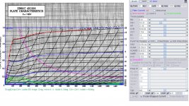
Here is Svetlana 4X150A/7034 model and sch if you need it.
options GminSteps=0
.options NoOpIter
.options SrcSteps=200
The Knee/Slope is sharp and is sensitive to accuracy of the sch in sim.
options GminSteps=0
.options NoOpIter
.options SrcSteps=200
The Knee/Slope is sharp and is sensitive to accuracy of the sch in sim.
Code:
**** 4X150A ***********************L1-3*******************
* Created on 02/16/2021 13:01 using paint_kip.jar
* [url=http://www.dmitrynizh.com/tubeparams_image.htm]Model Paint Tools: Trace Tube Parameters over Plate Curves, Interactively[/url]
* Plate Curves image file: 4x150a.png
* Data source link: <plate curves URL>
*----------------------------------------------------------------------------------
.SUBCKT 4X150A P G2 G K ; LTSpice tetrode.asy pinout
* .SUBCKT 4X150A P G K G2 ; Koren Pentode Pspice pinout
+ PARAMS: MU=8.28 KG1=1059.3 KP=21.48 KVB=5038.08 VCT=1.704 EX=1.4 KG2=41583.36 KNEE=20.88 KVC=3.752
+ KLAM=6.25E-9 KLAMG=8.91E-5  KD=1.231E6 KC=0.01918 KR1=0 KR2=0.1693 KVBG=0.00104 KB1=9.32 KB2=0 KB3=0 KB4=0.081 KVBGI=0.003125 KNK=0.0938 KNG=0.002097 KNPL=15.05 KNSL=37.38 KNPR=275.88 KNSR=84.22
+ CCG=15.7P CGP=0.04P CCP=4.5P VGOFF=-7.5 IGA=7.1E-4 IGB=0.084 IGC=15.52 IGEX=1.84
* Vp_MAX=1500 Ip_MAX=1400 Vg_step=20 Vg_start=20 Vg_count=18
* X_MIN=40 Y_MIN=29 X_SIZE=801 Y_SIZE=557 FSZ_X=1296 FSZ_Y=736 XYGrid=false
* Rp=1400 Vg_ac=20 P_max=250 Vg_qui=-150 Vp_qui=300
* showLoadLine=n showIp=y isDHP=n isPP=n isAsymPP=n isUL=n showDissipLimit=y
* showIg1=y isInputSnapped=y addLocalNFB=n
* XYProjections=n harmonicPlot=y dissipPlot=n
* UL=0.43 EG2=300 gridLevel2=y addKink=y isTanhKnee=n advSigmoid=y
*----------------------------------------------------------------------------------
RE1  7 0  1G    ; DUMMY SO NODE 7 HAS 2 CONNECTIONS
E1   7 0  VALUE=  ; E1 BREAKS UP LONG EQUATION FOR G1.
+{V(G2,K)/KP*LOG(1+EXP((1/MU+(VCT+V(G,K))/SQRT(KVB+V(G2,K)*V(G2,K)))*KP))}
RE2  6 0  1G    ; DUMMY SO NODE 6 HAS 2 CONNECTIONS
E2  6 0  VALUE={(PWR(V(7),EX)+PWRS(V(7),EX))} ; Kg1 times KIT current
E4   8 0  VALUE={V(P,K)/KNEE/(KVBGI+V(6)*KVBG)}
E5  81 0  VALUE={PWR(V(8),KB1)}
E6  82 0  VALUE={PWR(V(8),KB2)}
E7  83 0  VALUE={PWR(V(8),KB3)}
E8   9 0  VALUE={PWR(1-EXP(-V(81)*(KC+KR1*V(82))/(KD+KR2*V(83))),KB4)*1.5708}
RE4  8 0  1
RE5 81 0  1
RE6 82 0  1
RE7 83 0  1
RE8  9 0  1
RE21 21 0 1
E21  21 0 VALUE={V(6)/KG1*V(9)} ; Ip with knee but no slope and no kink
RE22 22 0 1 ; E22: kink curr deviation for plate
E22  22 0 VALUE={V(21)*LIMIT(KNK-V(G,K)*KNG,0,0.3)*(-ATAN((V(P,K)-KNPL)/KNSL)+ATAN((V(P,K)-KNPR)/KNSR))}
G1   P K  VALUE={V(21)*(1+KLAMG*V(P,K))+KLAM*V(P,K) + V(22)}
G2   G2 K  VALUE={V(6)/KG2*(KVC-V(9))/(1+KLAMG*V(P,K)) - V(22)}
RCP  P K  1G     ; FOR CONVERGENCE
C1   K G  {CCG}  ; CATHODE-GRID 1
C2   G P  {CGP}  ; GRID 1-PLATE
C3   K P  {CCP}  ; CATHODE-PLATE
RE23 G 0 1G
GG G K VALUE={(IGA+IGB/(IGC+V(P,K)))*(MU/KG1)*
+(PWR(V(G,K)-VGOFF,IGEX)+PWRS(V(G,K)-VGOFF,IGEX))}
.ENDS
*$
Attachments
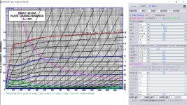
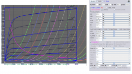
Ia in left side scale of the above model is wrong, now corrected and it's Eimac 4-150A model.
Code:
**** 4X150A *********************L1-3*********************
* Created on 02/16/2021 14:25 using paint_kip.jar
* [url=http://www.dmitrynizh.com/tubeparams_image.htm]Model Paint Tools: Trace Tube Parameters over Plate Curves, Interactively[/url]
* Plate Curves image file: 4x150a.png
* Data source link: <plate curves URL>
*----------------------------------------------------------------------------------
.SUBCKT 4X150A P G2 G K ; LTSpice tetrode.asy pinout
* .SUBCKT 4X150A P G K G2 ; Koren Pentode Pspice pinout
+ PARAMS: MU=8.28 KG1=741.51 KP=21.48 KVB=5038.08 VCT=1.704 EX=1.4 KG2=23761.92 KNEE=20.88 KVC=3.752
+ KLAM=6.25E-9 KLAMG=8.91E-5  KD=1.589E-4 KC=0.01676 KR1=0.002223 KR2=0.0576 KVBG=0.006022 KB1=5.84 KB2=1.34 KB3=0.73 KB4=0.162 KVBGI=0.00118 KNK=0.091 KNG=0.00233 KNPL=3.225 KNSL=46.25 KNPR=278.16 KNSR=86.77
+ CCG=15.7P CGP=0.04P CCP=4.5P VGOFF=-7.5 IGA=7.1E-4 IGB=0.084 IGC=15.52 IGEX=1.84
* Vp_MAX=1500 Ip_MAX=1400 Vg_step=20 Vg_start=20 Vg_count=18
* X_MIN=40 Y_MIN=196 X_SIZE=801 Y_SIZE=390 FSZ_X=1296 FSZ_Y=736 XYGrid=false
* Rp=1400 Vg_ac=20 P_max=250 Vg_qui=-150 Vp_qui=300
* showLoadLine=n showIp=y isDHP=n isPP=n isAsymPP=n isUL=n showDissipLimit=y
* showIg1=y isInputSnapped=y addLocalNFB=n
* XYProjections=n harmonicPlot=y dissipPlot=n
* UL=0.43 EG2=300 gridLevel2=y addKink=y isTanhKnee=n advSigmoid=y
*----------------------------------------------------------------------------------
RE1  7 0  1G    ; DUMMY SO NODE 7 HAS 2 CONNECTIONS
E1   7 0  VALUE=  ; E1 BREAKS UP LONG EQUATION FOR G1.
+{V(G2,K)/KP*LOG(1+EXP((1/MU+(VCT+V(G,K))/SQRT(KVB+V(G2,K)*V(G2,K)))*KP))}
RE2  6 0  1G    ; DUMMY SO NODE 6 HAS 2 CONNECTIONS
E2  6 0  VALUE={(PWR(V(7),EX)+PWRS(V(7),EX))} ; Kg1 times KIT current
E4   8 0  VALUE={V(P,K)/KNEE/(KVBGI+V(6)*KVBG)}
E5  81 0  VALUE={PWR(V(8),KB1)}
E6  82 0  VALUE={PWR(V(8),KB2)}
E7  83 0  VALUE={PWR(V(8),KB3)}
E8   9 0  VALUE={PWR(1-EXP(-V(81)*(KC+KR1*V(82))/(KD+KR2*V(83))),KB4)*1.5708}
RE4  8 0  1
RE5 81 0  1
RE6 82 0  1
RE7 83 0  1
RE8  9 0  1
RE21 21 0 1
E21  21 0 VALUE={V(6)/KG1*V(9)} ; Ip with knee but no slope and no kink
RE22 22 0 1 ; E22: kink curr deviation for plate
E22  22 0 VALUE={V(21)*LIMIT(KNK-V(G,K)*KNG,0,0.3)*(-ATAN((V(P,K)-KNPL)/KNSL)+ATAN((V(P,K)-KNPR)/KNSR))}
G1   P K  VALUE={V(21)*(1+KLAMG*V(P,K))+KLAM*V(P,K) + V(22)}
G2   G2 K  VALUE={V(6)/KG2*(KVC-V(9))/(1+KLAMG*V(P,K)) - V(22)}
RCP  P K  1G     ; FOR CONVERGENCE
C1   K G  {CCG}  ; CATHODE-GRID 1
C2   G P  {CGP}  ; GRID 1-PLATE
C3   K P  {CCP}  ; CATHODE-PLATE
RE23 G 0 1G
GG G K VALUE={(IGA+IGB/(IGC+V(P,K)))*(MU/KG1)*
+(PWR(V(G,K)-VGOFF,IGEX)+PWRS(V(G,K)-VGOFF,IGEX))}
.ENDS
*$
Attachments
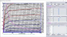
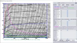
This 4X150A RCA model, work without any options:
Code:
**** 4X150A *******************RCA-7***********************
* Created on 02/17/2021 15:16 using paint_kip.jar
* [URL="http://www.dmitrynizh.com/tubeparams_image.htm"]Model Paint Tools: Trace Tube Parameters over Plate Curves, Interactively[/URL]
* Plate Curves image file: 4x150a.png
* Data source link: <plate curves URL>
*----------------------------------------------------------------------------------
.SUBCKT 4X150A P G2 G K ; LTSpice tetrode.asy pinout
* .SUBCKT 4X150A P G K G2 ; Koren Pentode Pspice pinout
+ PARAMS: MU=5.913 KG1=2283.64 KP=19.38 KVB=5038.08 VCT=-5.253 EX=1.669 KG2=6032.41 KNEE=1881.54 KVC=1.954
+ KLAM=4.043E-12 KLAMG=6.77E-5 KNEE2=50.56 KNEX=4.795E7  KNK=0.1336 KNG=0.001604 KNPL=0.04744 KNSL=176.92 KNPR=243.07 KNSR=91.92
+ CCG=16P CGP=0.03P CCP=4.4P VGOFF=-7.5 IGA=7.1E-4 IGB=0.084 IGC=15.52 IGEX=1.84
* Vp_MAX=2000 Ip_MAX=1600 Vg_step=10 Vg_start=30 Vg_count=17
* X_MIN=60 Y_MIN=27 X_SIZE=718 Y_SIZE=574 FSZ_X=1296 FSZ_Y=736 XYGrid=false
* Rp=1400 Vg_ac=20 P_max=250 Vg_qui=-50 Vp_qui=300
* showLoadLine=n showIp=y isDHP=n isPP=n isAsymPP=n isUL=n showDissipLimit=y
* showIg1=y isInputSnapped=y addLocalNFB=n
* XYProjections=n harmonicPlot=y dissipPlot=n
* UL=0.43 EG2=250 gridLevel2=y addKink=y isTanhKnee=y advSigmoid=n
*----------------------------------------------------------------------------------
RE1  7 0  1G    ; DUMMY SO NODE 7 HAS 2 CONNECTIONS
E1   7 0  VALUE=  ; E1 BREAKS UP LONG EQUATION FOR G1.
+{V(G2,K)/KP*LOG(1+EXP((1/MU+(VCT+V(G,K))/SQRT(KVB+V(G2,K)*V(G2,K)))*KP))}
RE2  6 0  1G    ; DUMMY SO NODE 6 HAS 2 CONNECTIONS
E2  6 0  VALUE={(PWR(V(7),EX)+PWRS(V(7),EX))} ; Kg1 times KIT current
RE21 21 0 1
E21  21 0 VALUE={V(6)/KG1*ATAN((V(P,K)+KNEX)/KNEE)*TANH(V(P,K)/KNEE2)} ; Ip with knee but no slope and no kink
RE22 22 0 1 ; E22: kink curr deviation for plate
E22  22 0 VALUE={V(21)*LIMIT(KNK-V(G,K)*KNG,0,0.3)*(-ATAN((V(P,K)-KNPL)/KNSL)+ATAN((V(P,K)-KNPR)/KNSR))}
G1   P  K  VALUE={V(21)*(1+KLAMG*V(P,K))+KLAM*V(P,K) + V(22)}
* Alexander Gurskii screen current, see audioXpress 2/2011, with slope and kink added
RE43 43 K 1G ; Dummy
E43  43 G2 VALUE={0} ; Dummy
G2   43 K  VALUE={V(6)/KG2*(KVC-ATAN((V(P,K)+KNEX)/KNEE)*TANH(V(P,K)/KNEE2))/(1+KLAMG*V(P,K))-V(22)}
RCP  P K  1G     ; FOR CONVERGENCE
C1   K G  {CCG}  ; CATHODE-GRID 1
C2   G P  {CGP}  ; GRID 1-PLATE
C3   K P  {CCP}  ; CATHODE-PLATE
RE23 G 0 1G
GG G K VALUE={(IGA+IGB/(IGC+V(P,K)))*(MU/KG1)*
+(PWR(V(G,K)-VGOFF,IGEX)+PWRS(V(G,K)-VGOFF,IGEX))}
.ENDS
*$
Attachments
Posted a query in the other spice thread. I’m just trying to model a prospective 6AS7 amp designed by @suncalc. I couldn’t find a proper audio potentiometer model so consulted the wiki and YouTube. I came up with the attached and by luck it seems to work. I don’t know how an actual audio pot is supposed to behave and would appreciate any advice to improve it and fix errors. Thanks. https://www.diyaudio.com/forums/sof...ltxvii-beginner-advanced-259.html#post6528950
- Home
- Amplifiers
- Tubes / Valves
- Vacuum Tube SPICE Models