Hi Artema
Because of changed circumstances/priorities, I can't build this model - sorry! Perhaps later...
Hello Artemka
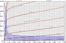
I have now found a slot to fit my generic triode model to the 811A RCA data sheet.
But to finish/complete the model, some further information would be helpful, because the data sheet has no traces for negative Vg...
If you have a 811A sample available, would you please be so kind and measure
1) if possible the heaters resistance (when cold)
2) if possible also the heaters steady state current at 6.3V
3) if possible the anode current with grounded grid at Va= 50V and 100V
That would be perfect
Thanks in advance, Adrian
Because of changed circumstances/priorities, I can't build this model - sorry! Perhaps later...
Hello Artemka
I have now found a slot to fit my generic triode model to the 811A RCA data sheet.
But to finish/complete the model, some further information would be helpful, because the data sheet has no traces for negative Vg...
If you have a 811A sample available, would you please be so kind and measure
1) if possible the heaters resistance (when cold)
2) if possible also the heaters steady state current at 6.3V
3) if possible the anode current with grounded grid at Va= 50V and 100V
That would be perfect
Thanks in advance, Adrian
Hi Artemka
There seems no further information available in the web about the 811A's behavior at neg. Vg.
So, I finished my model with a hint to the unknown accuracy for neg. Vg.
As my spice code is a bit larger than common triode model code, it would be an overkill to insert it in this forum. You will find my model on my website:
http://adrianimmler.simplesite.com/440956786
all the best, Adrian
Attachments
And maybe ck5886 (or ck 5889)? These are electrometer tubes, used in GM- detectors. I want to use it for measuring various component leakages, not audio. Is it possible to model G1 current as in the datasheet? Looks like a parabola with a minimum and possibly two zero-current points... I'd appreciate any help.Jazbo any chance for 2e22? Thanks
Last edited:
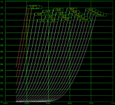
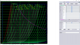
This model is based on solely on the data published on Tube Tester Files - EL82, EL84, EL86 Soviet Clones, maybe there are some differences. 0.5w dissipation is for relative reference the actual is about same as el84(?).
Code:
**** 6P43P_LOW ******************************************
* Created on 03/28/2019 11:53 using paint_kit.jar 3.1
* [URL="http://www.dmitrynizh.com/tubeparams_image.htm"]Model Paint Tools: Trace Tube Parameters over Plate Curves, Interactively[/URL]
* Plate Curves image file: 6p43p_low.png
* Data source link:
*----------------------------------------------------------------------------------
.SUBCKT 6P43P_LOW 1 2 3 ; Plate Grid Cathode
+ PARAMS: CCG=3P  CGP=1.4P CCP=1.9P RGI=2000
+ MU=7.416 KG1=1161.22 KP=21.22 KVB=127.71 VCT=0 EX=1.663
* Vp_MAX=100 Ip_MAX=15 Vg_step=1 Vg_start=1 Vg_count=12
* Rp=4000 Vg_ac=55 P_max=0.5 Vg_qui=-48 Vp_qui=300
* X_MIN=46 Y_MIN=57 X_SIZE=847 Y_SIZE=738 FSZ_X=1550 FSZ_Y=878 XYGrid=false
* showLoadLine=n showIp=y isDHT=n isPP=n isAsymPP=n showDissipLimit=y
* showIg1=n gridLevel2=n isInputSnapped=n
* XYProjections=n harmonicPlot=n dissipPlot=n
*----------------------------------------------------------------------------------
E1 7 0 VALUE={V(1,3)/KP*LOG(1+EXP(KP*(1/MU+(VCT+V(2,3))/SQRT(KVB+V(1,3)*V(1,3)))))}
RE1 7 0 1G  ; TO AVOID FLOATING NODES
G1 1 3 VALUE={(PWR(V(7),EX)+PWRS(V(7),EX))/KG1}
RCP 1 3 1G   ; TO AVOID FLOATING NODES
C1 2 3 {CCG} ; CATHODE-GRID
C2 2 1 {CGP} ; GRID=PLATE
C3 1 3 {CCP} ; CATHODE-PLATE
D3 5 3 DX ; POSITIVE GRID CURRENT
R1 2 5 {RGI} ; POSITIVE GRID CURRENT
.MODEL DX D(IS=1N RS=1 CJO=10PF TT=1N)
.ENDS
*$
Attachments
Last edited:
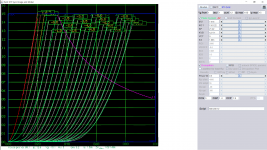
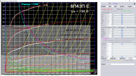
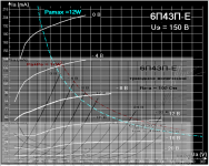
The following 6p43p model has the Pentode, screen and triode curve combined, you can plot the triode curve using the lower scale of interest to see how it compared with the tester plot. Data source: http://tec.org.ru/_bd/17/1764_643-.pdf
Code:
**** 6P43P ******************************************
* Created on 03/28/2019 16:15 using paint_kip.jar
* [url=http://www.dmitrynizh.com/tubeparams_image.htm]Model Paint Tools: Trace Tube Parameters over Plate Curves, Interactively[/url]
* Plate Curves image file: 6p43p.png
* Data source link: <plate curves URL>
*----------------------------------------------------------------------------------
.SUBCKT 6P43P P G2 G K ; LTSpice tetrode.asy pinout
* .SUBCKT 6P43P P G K G2 ; Koren Pentode Pspice pinout
+ PARAMS: MU=7.875 KG1=2447.4 KP=46.17 KVB=230.21 VCT=1.997 EX=1.671 KG2=4140.36 KNEE=13.23 KVC=1.645
+ KLAM=5.047E-9 KLAMG=3.66E-4   KNK=-0.044 KNG=0.006 KNPL=50 KNSL=11 KNPR=120 KNSR=29
+ CCG=1.3P CGP=0.7P CCP=9P RGI=2000.0
* Vp_MAX=380 Ip_MAX=216 Vg_step=4 Vg_start=0 Vg_count=10
* X_MIN=58 Y_MIN=11 X_SIZE=1012 Y_SIZE=787 FSZ_X=1550 FSZ_Y=878 XYGrid=false
* Rp=1400 Vg_ac=20 P_max=14 Vg_qui=-18 Vp_qui=300
* showLoadLine=n showIp=y isDHP=n isPP=n isAsymPP=n isUL=n showDissipLimit=y
* showIg1=n isInputSnapped=y addLocalNFB=n
* XYProjections=n harmonicPlot=y dissipPlot=n
* UL=0.43 EG2=150 gridLevel2=n addKink=y isTanhKnee=n advSigmoid=n
*----------------------------------------------------------------------------------
RE1  7 0  1G    ; DUMMY SO NODE 7 HAS 2 CONNECTIONS
E1   7 0  VALUE=  ; E1 BREAKS UP LONG EQUATION FOR G1.
+{V(G2,K)/KP*LOG(1+EXP((1/MU+(VCT+V(G,K))/SQRT(KVB+V(G2,K)*V(G2,K)))*KP))}
RE2  6 0  1G    ; DUMMY SO NODE 6 HAS 2 CONNECTIONS
E2  6 0  VALUE={(PWR(V(7),EX)+PWRS(V(7),EX))} ; Kg1 times KIT current
RE21 21 0 1
E21  21 0 VALUE={V(6)/KG1*ATAN(V(P,K)/KNEE)} ; Ip with knee but no slope and no kink
RE22 22 0 1 ; E22: kink curr deviation for plate
E22  22 0 VALUE={V(21)*LIMIT(KNK-V(G,K)*KNG,0,0.3)*(-ATAN((V(P,K)-KNPL)/KNSL)+ATAN((V(P,K)-KNPR)/KNSR))}
G1   P  K  VALUE={V(21)*(1+KLAMG*V(P,K))+KLAM*V(P,K) + V(22)}
* Alexander Gurskii screen current, see audioXpress 2/2011, with slope and kink added
RE43 43 K 1G ; Dummy
E43  43 G2 VALUE={0} ; Dummy
G2   43 K  VALUE={V(6)/KG2*(KVC-ATAN(V(P,K)/KNEE))/(1+KLAMG*V(P,K))-V(22)}
RCP  P K  1G     ; FOR CONVERGENCE
C1   K G  {CCG}  ; CATHODE-GRID 1
C2   G P  {CGP}  ; GRID 1-PLATE
C3   K P  {CCP}  ; CATHODE-PLATE
R1   G 5  {RGI}  ; FOR GRID CURRENT
D3   5 K  DX     ; FOR GRID CURRENT }
.MODEL DX D(IS=1N RS=1 CJO=10PF TT=1N)
.ENDS
*$


* The following triode model is derived from pentode model, see above.
* In the triode model, all spice parameters come directly from the pentode model, except for Kg1,
* which for triode-strapped pentodes is derived from pentode's Kg1, Kg2 and Kvc as
*
*    4Kg1Kg2 / ((2Kvc-Pi)(2Kg1+PiKg2))

**** 6P43P ******************************************
* Created on 03/28/2019 16:15 using paint_kit.jar 4.7
* [url=http://www.dmitrynizh.com/tubeparams_image.htm]Model Paint Tools: Trace Tube Parameters over Plate Curves, Interactively[/url]
* Plate Curves image file: 6p43p.png
* Data source link: <plate curves URL>
*----------------------------------------------------------------------------------
.SUBCKT TRIODE_6P43P 1 2 3 ; Plate Grid Cathode
+ PARAMS: CCG=1.3P  CGP=0.7P CCP=9P RGI=2000
+ MU=7.875 KG1=15256.81 KP=46.17 KVB=230.21 VCT=1.997 EX=1.671
* Vp_MAX=380 Ip_MAX=216 Vg_step=4 Vg_start=0 Vg_count=10
* Rp=1400 Vg_ac=20 P_max=14 Vg_qui=-18 Vp_qui=300
* X_MIN=58 Y_MIN=11 X_SIZE=1012 Y_SIZE=787 FSZ_X=1550 FSZ_Y=878 XYGrid=false
* showLoadLine=n showIp=y isDHT=n isPP=n isAsymPP=n showDissipLimit=y
* showIg1=n gridLevel2=n isInputSnapped=y
* XYProjections=n harmonicPlot=y dissipPlot=n
*----------------------------------------------------------------------------------
E1 7 0 VALUE={V(1,3)/KP*LOG(1+EXP(KP*(1/MU+(VCT+V(2,3))/SQRT(KVB+V(1,3)*V(1,3)))))}
RE1 7 0 1G  ; TO AVOID FLOATING NODES
G1 1 3 VALUE={(PWR(V(7),EX)+PWRS(V(7),EX))/KG1}
RCP 1 3 1G   ; TO AVOID FLOATING NODES
C1 2 3 {CCG} ; CATHODE-GRID
C2 2 1 {CGP} ; GRID=PLATE
C3 1 3 {CCP} ; CATHODE-PLATE
D3 5 3 DX ; POSITIVE GRID CURRENT
R1 2 5 {RGI} ; POSITIVE GRID CURRENT
.MODEL DX D(IS=1N RS=1 CJO=10PF TT=1N)
.ENDS
*$
Attachments
Courtesy of jazbo8 the Ayumi SPICE model library:
Files included, copyrighted material, if you distribute these files make sure that the first three lines are not removed.
PSpice Models => View attachment 638558
A time-saver, the file below contains all the Ayumi SPICE models that are compatible with LTspice - manual editing of the files is no longer required!
LTspice Models => View attachment 689353 (New 06/29/2018)
The 6KG6.inc file in this library is blank (no text at all in the archived file).
I can't seem to find a 6KG6 or EL509 model anywhere else in this thread. Is there one somewhere that I missed?
Is 6LF6 equivalent? Maybe 'close enough'?
Thanks.
--
Last edited:
The 6KG6.inc file in this library is blank (no text at all in the archived file).
I can't seem to find a 6KG6 or EL509 model anywhere else in this thread. Is there one somewhere that I missed?
Is 6LF6 equivalent? Maybe 'close enough'?
Thanks.
--
.SUBCKT SVEL509 1 2 3 4 ; A G2 G1 C (Beam Tetrode)
* Svetlana's Data sheet AKA 6KG6
* library format: LTSpice 29-May-2008
X1 1 2 3 4 PENTODE1 MU=8.08 EX=1.350 KG1=263.9 KG2=4500 KP=11.68 KVB=42.1 VCT=0.00 RGI=1000 CCG=10.0p CPG1=3.0p CCP=6.5p ;
.ENDS SVEL509
The above needs the following sub-circuit to work:
Code:
.SUBCKT PENTODE1 1 2 3 4
+ MU=35.04 EX=1.350 KG1=2242.2 KG2=4500 KP=221.86 KVB=7.1
+ VCT=0.00 RGI=2000 CCG=4.3p CPG1=0.6p CCP=5.1p
RE1  7 0  1MEG    ; DUMMY SO NODE 7 HAS 2 CONNECTIONS
E1   7 0  VALUE={V(2,4)/KP*LOG(1+EXP((1/MU+V(3,4)/V(2,4))*KP))} ; E1 BREAKS UP LONG EQUATION FOR G1.
G1   1 4  VALUE={(PWR(V(7),EX)+PWRS(V(7),EX))/KG1*ATAN(V(1,4)/KVB)}
G2   2 4 VALUE={(V(2,4)/MU)+V(3,4) > 0 ? (EXP(EX*(LOG((V(2,4)/MU)+V(3,4)))))/KG2 : 0}
RCP  1 4  1G      ; FOR CONVERGENCE A  - C
C1   3 4  {CCG}   ; CATHODE-GRID 1  C  - G1
C2   1 3  {CPG1}  ; GRID 1-PLATE    G1 - A
C3   1 4  {CCP}   ; CATHODE-PLATE   A  - C
R1   3 5  {RGI}   ; FOR GRID CURRENT    G1 - 5
D3   5 4  DX      ; FOR GRID CURRENT    5  - C
.MODEL DX D(IS=1N RS=1 CJO=10PF TT=1N) ;
.ENDS PENTODE1Thanks for this.
Can one simply concatenate the two .SUBCKT into a single text file and link to an .sym file to make a model? Or does this have to be done using the PENTODE1 sub-circuit and load in the SVEL509 model from a drop-down?
I'll try mucking with it when I get home this evening...
Can one simply concatenate the two .SUBCKT into a single text file and link to an .sym file to make a model? Or does this have to be done using the PENTODE1 sub-circuit and load in the SVEL509 model from a drop-down?
I'll try mucking with it when I get home this evening...
Dear Adrian, thanks for the good model with excellent comments!So, I finished my model with a hint to the unknown accuracy for neg. Vg.
However during the model import to ADS I get such warnings:
WARNING: Skipping unsupported statement ".params", line #17.WARNING: Appended "_n" to node v due to a conflict with a reserved word.
Element name = is changed to x
WARNING: Appended "_n" to node v due to a conflict with a reserved word.
WARNING: Appended "_n" to node v due to a conflict with a reserved word.
WARNING: Appended "_n" to node i due to a conflict with a reserved word.
WARNING: Appended "_n" to node i due to a conflict with a reserved word.
WARNING: Appended "_n" to node i due to a conflict with a reserved word.
WARNING: Appended "_n" to node i due to a conflict with a reserved word.
WARNING: Appended "_n" to node i due to a conflict with a reserved word.
WARNING: Model "x" for device "bggi" in circuit "811a_i3d" not found.
WARNING: Model "x" for device "bahc" in circuit "811a_i3d" not found.
WARNING: Model "x" for device "bst" in circuit "811a_i3d" not found.
WARNING: Model "x" for device "bs" in circuit "811a_i3d" not found.
WARNING: Model "x" for device "bgl" in circuit "811a_i3d" not found.
WARNING: Model "x" for device "bgvd" in circuit "811a_i3d" not found.
WARNING: Model "x" for device "bgr" in circuit "811a_i3d" not found.
WARNING: Model "x" for device "bs0" in circuit "811a_i3d" not found.
UPD to my previous post.
probably the issue is that ADS doesn't work properly with ltspice models. Only pspice models are supported. Do you know how to convert ltspice 2 pspice?
BR
Artem
Hi ArtemDear Adrian, thanks for the good model with excellent comments!
[...] Do you know how to convert ltspice 2 pspice?
You are welcome!
Regarding the conversion to pspice: I actually never used another spice tool than LTspice, so I'm not familiar with other spice dialects - sorry! But for sure there will be competent help for you in this forum...
all the best, Adrian
My spice models are now at a new web site
As Earthlink "killed" my Netcom hosted web pages, I relocated my spice models to
http://www.wa2ise.com/netcom/spice.txt
and http://www.wa2ise.com/netcom/spice4.txt
And my other web pages that were at Netcom are now at
WA2ISE Links page
including the web page about building tube circuits for the analog portion of CD players. Modifying CD player DAC circuits
Try this:
Code:
.SUBCKT D3A_Triode 1 2 3 ; P G K ;  (A.Moglia 12.2.13.)
+ PARAMS: CCG=6.7P CGP=3.3P CCP=1P RGI=2000
+ MU=72.1 EX=1.456 KG1=65.625 KP=534.0 KVB=300.0 VCT=0.0557 ; Vp_MAX=500.0 Ip_MAX=0.07 Vg_step=0.5
*--------------------------------------------------
E1 7 0 VALUE={V(1,3)/KP*LOG(1+EXP(KP*(1/MU+(VCT+V(2,3))/SQRT(KVB+V(1,3)*V(1,3)))))}
RE1 7 0 1G
G1 1 3 VALUE={(PWR(V(7),EX)+PWRS(V(7),EX))/KG1}
RCP 1 3 1G ; TO AVOID FLOATING NODES
C1 2 3 {CCG} ; CATHODE-GRID
C2 2 1 {CGP} ; GRID=PLATE
C3 1 3 {CCP} ; CATHODE-PLATE
D3 5 3 DX ; FOR GRID CURRENT
R1 2 5 {RGI} ; FOR GRID CURRENT
.MODEL DX D(IS=1N RS=1 CJO=10PF TT=1N)
.ENDS


*
* Generic pentode model: D3A_AN
* Copyright 2003--2008 by Ayumi Nakabayashi, All rights reserved.
* Version 3.10, Generated on Mon Dec 23 07:04:01 2013
*              Plate
*              | Screen Grid
*              | |  Control Grid
*              | |  |  Cathode
*              | |  |  |
.SUBCKT D3A_P  A G2 G1 K
BGG  GG  0 V=V(G1,K)+0.38087015
BM1  M1  0 V=(0.0021582473*(URAMP(V(G2,K))+1e-10))**-0.28773641
BM2  M2  0 V=(0.83904987*(URAMP(V(GG)+URAMP(V(G2,K))/74.574462)))**1.7877364
BP    P    0 V=0.03039942*(URAMP(V(GG)+URAMP(V(G2,K))/88.879654))**1.5
BIK  IK  0 V=U(V(GG))*V(P)+(1-U(V(GG)))*0.018902992*V(M1)*V(M2)
BIG  IG  0 V=0.01519971*URAMP(V(G1,K))**1.5*(URAMP(V(G1,K))/(URAMP(V(A,K))+URAMP(V(G1,K)))*1.2+0.4)
BIK2  IK2  0 V=V(IK,IG)*(1-0.4*(EXP(-URAMP(V(A,K))/URAMP(V(G2,K))*15)-EXP(-15)))
BIG2T IG2T 0 V=V(IK2)*(0.79212298*(1-URAMP(V(A,K))/(URAMP(V(A,K))+10))**1.5+0.20787702)
BIK3  IK3  0 V=V(IK2)*(URAMP(V(A,K))+4970)/(URAMP(V(G2,K))+4970)
BIK4  IK4  0 V=V(IK3)-URAMP(V(IK3)-(0.015714194*(URAMP(V(A,K))+URAMP(URAMP(V(G2,K))-URAMP(V(A,K))))**1.5))
BIP  IP  0 V=URAMP(V(IK4,IG2T)-URAMP(V(IK4,IG2T)-(0.015714194*URAMP(V(A,K))**1.5)))
BIAK  A    K I=V(IP)+1e-10*V(A,K)
BIG2  G2  K I=URAMP(V(IK4,IP))
BIGK  G1  K I=V(IG)
* CAPS
CGA  G1  A  0.035p
CGK  G1  K  4.1p
C12  G1  G2 2.7p
CAK  A  K  0p
.ENDS- Home
- Amplifiers
- Tubes / Valves
- Vacuum Tube SPICE Models