Hey Ian,
I generally run the 6S3P at between 7 - 12mA with good results.
Why so high?
Cheers
Ian
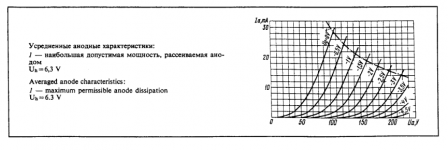
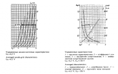
Linearity and noise performance mainly. It's designed to operate at relatively high currents (recommended up to 15mA) and linearity is not great at low currents. I also want to run them in the high transconductance region of their characteristic curves, I use them in low noise phono stages..
Attachments
Linearity and noise performance mainly. It's designed to operate at relatively high currents (recommended up to 15mA) and linearity is not great at low currents. I also want to run them in the high transconductance region of their characteristic curves, I use them in low noise phono stages..
Interesting. What plate/cathode voltage are you using.
For my application linearity is not a big issue since the signal level is small and there is global NFB. My plan is to run it at 100V Vak, -1.6 Vgc and Ia of 1mA which still gives a gm of 20mA/V.
Cheers
Ian

Code:
.SUBCKT 6973  1 2 3 4 ; A G2 G1 C (Pentode)
* RCA data sheet
* library format: LTSpice 14-Nov-2009
+PARAMS: MU=13.58 EX=1.350 KG1=1142.2 KG2=4500 KP=27.70 KVB=18.4 VCT=0.00 RGI=2000 CCG=4.3p CPG1=0.6p CCP=5.1p
RE1  7 0  1MEG    ; DUMMY SO NODE 7 HAS 2 CONNECTIONS
E1   7 0  VALUE={V(2,4)/KP*LOG(1+EXP((1/MU+V(3,4)/V(2,4))*KP))} ; E1 BREAKS UP LONG EQUATION FOR G1.
G1   1 4  VALUE={(PWR(V(7),EX)+PWRS(V(7),EX))/KG1*ATAN(V(1,4)/KVB)}
G2   2 4  VALUE={(EXP(EX*(LOG((V(2,4)/MU)+V(3,4)))))/KG2}
*G2   2 4  VALUE={PWR(if( V(2,4)/MU+V(3,4) < 0 , V(2,4)/MU+V(3,4), 0 ) ,EX )/KG2}
*G2   2 4  VALUE={(PWR(V(7),EX)+PWRS(V(7),EX))/KG2*(2.5708-ATAN(V(1,3)/KVB))}
RCP  1 4  1G      ; FOR CONVERGENCE    A  - C
C1   3 4  {CCG}   ; CATHODE-GRID 1    C  - G1
C2   1 3  {CPG1}  ; GRID 1-PLATE    G1 - A
C3   1 4  {CCP}   ; CATHODE-PLATE    A  - C
R1   3 5  {RGI}   ; FOR GRID CURRENT    G1 - 5
D3   5 4  DX      ; FOR GRID CURRENT    5  - C
.MODEL DX D(IS=1N RS=1 CJO=10PF TT=1N) ;
.ENDSCurious, but from which Russian data-book/sheet did those 6S3P curves come from?
I have several, but the one I referred to specifically in this case is available here:
http://www.mif.pg.gda.pl/homepages/frank/sheets/112/6/6S3PEV.pdf
I do not know the specific origin of this data sheet, most Soviet era data sheets do not list specific vendors. It probably came out of some design bureau in Moscow or St. Petersburg. Russian language data sheets are packed with these tubes, complete with inspection stamp which is both on the tube and the data sheet.. (And the symbol for Reflektor, the only maker I have identified for the EV version)
Bear in mind that these are in fact Military surplus types, and U.S. industrial/milspec tubes have similarly or even more comprehensive data sheets. A good example would be the data sheet for the Raytheon 5842 here:
http://www.mif.pg.gda.pl/homepages/frank/sheets/138/5/5842.pdf
And the WE 417A here: http://www.westernelectric.com/spec_sheets/417A.pdf
http://www.mif.pg.gda.pl/homepages/frank/sheets/138/5/5842.pdf
And the WE 417A here: http://www.westernelectric.com/spec_sheets/417A.pdf
Thank you very much cogsncogs, this is a very good tube.Code:.SUBCKT 6973 1 2 3 4 ; A G2 G1 C (Pentode) * RCA data sheet * library format: LTSpice 14-Nov-2009 +PARAMS: MU=13.58 EX=1.350 KG1=1142.2 KG2=4500 KP=27.70 KVB=18.4 VCT=0.00 RGI=2000 CCG=4.3p CPG1=0.6p CCP=5.1p RE1 7 0 1MEG ; DUMMY SO NODE 7 HAS 2 CONNECTIONS E1 7 0 VALUE={V(2,4)/KP*LOG(1+EXP((1/MU+V(3,4)/V(2,4))*KP))} ; E1 BREAKS UP LONG EQUATION FOR G1. G1 1 4 VALUE={(PWR(V(7),EX)+PWRS(V(7),EX))/KG1*ATAN(V(1,4)/KVB)} G2 2 4 VALUE={(EXP(EX*(LOG((V(2,4)/MU)+V(3,4)))))/KG2} *G2 2 4 VALUE={PWR(if( V(2,4)/MU+V(3,4) < 0 , V(2,4)/MU+V(3,4), 0 ) ,EX )/KG2} *G2 2 4 VALUE={(PWR(V(7),EX)+PWRS(V(7),EX))/KG2*(2.5708-ATAN(V(1,3)/KVB))} RCP 1 4 1G ; FOR CONVERGENCE A - C C1 3 4 {CCG} ; CATHODE-GRID 1 C - G1 C2 1 3 {CPG1} ; GRID 1-PLATE G1 - A C3 1 4 {CCP} ; CATHODE-PLATE A - C R1 3 5 {RGI} ; FOR GRID CURRENT G1 - 5 D3 5 4 DX ; FOR GRID CURRENT 5 - C .MODEL DX D(IS=1N RS=1 CJO=10PF TT=1N) ; .ENDS
")
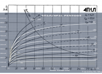
4P1L UL Characteristic & SPICE Model
Someone asked for the UL characteristic for 4P1L, here is one with 40% tap:
Here is the SPICE model based on the datasheet found here.
Someone asked for the UL characteristic for 4P1L, here is one with 40% tap:
An externally hosted image should be here but it was not working when we last tested it.
Here is the SPICE model based on the datasheet found here.
Code:
*
* Generic pentode model: 4P1L_AN
* Copyright 2003--2008 by Ayumi Nakabayashi, All rights reserved.
* Version 3.10, Generated on Wed Jan 08 17:33:48 2014
*               Plate
*               | Screen Grid
*               | |  Control Grid
*               | |  |  Cathode
*               | |  |  |
.SUBCKT 4P1L_AN A G2 G1 K
BGG   GG   0 V=V(G1,K)+1
BM1   M1   0 V=(0.020703576*(URAMP(V(G2,K))+1e-10))**-0.32815356
BM2   M2   0 V=(0.8205*(URAMP(V(GG)+URAMP(V(G2,K))/8.67)))**1.8281536
BP    P    0 V=0.0016959897*(URAMP(V(GG)+URAMP(V(G2,K))/10.566728))**1.5
BIK   IK   0 V=U(V(GG))*V(P)+(1-U(V(GG)))*0.00103*V(M1)*V(M2)
BIG   IG   0 V=0.00084799486*URAMP(V(G1,K))**1.5*(URAMP(V(G1,K))/(URAMP(V(A,K))+URAMP(V(G1,K)))*1.2+0.4)
BIK2  IK2  0 V=V(IK,IG)*(1-0.4*(EXP(-URAMP(V(A,K))/URAMP(V(G2,K))*15)-EXP(-15)))
BIG2T IG2T 0 V=V(IK2)*(0.857*(1-URAMP(V(A,K))/(URAMP(V(A,K))+10))**1.5+0.143)
BIK3  IK3  0 V=V(IK2)*(URAMP(V(A,K))+908)/(URAMP(V(G2,K))+908)
BIK4  IK4  0 V=V(IK3)-URAMP(V(IK3)-(0.0010943584*(URAMP(V(A,K))+URAMP(URAMP(V(G2,K))-URAMP(V(A,K))))**1.5))
BIP   IP   0 V=URAMP(V(IK4,IG2T)-URAMP(V(IK4,IG2T)-(0.0010943584*URAMP(V(A,K))**1.5)))
BIAK  A    K I=V(IP)+1e-10*V(A,K)
BIG2  G2   K I=URAMP(V(IK4,IP))
BIGK  G1   K I=V(IG)
* CAPS
CGA   G1  A  0.1p
CGK   G1  K  5.6p
C12   G1  G2 3.7p
CAK   A   K  8.5p
.ENDS
Last edited:
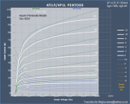
Freshly traced 4P1L with uTracer. Will create new models for triode-mode with starved filaments. Here is the Pentode curves:
4?1? / 4P1L Pentode Curves | Bartola Valves
@jackinnj , jazbo8 and all the pentode experts. Can you please kindly generate a more accurate model using your math magic?
Thanks,
Ale
4?1? / 4P1L Pentode Curves | Bartola Valves
@jackinnj , jazbo8 and all the pentode experts. Can you please kindly generate a more accurate model using your math magic?
Thanks,
Ale
Freshly traced 4P1L with uTracer. Will create new models for triode-mode with starved filaments.
Thanks,
Ale
These are very nice looking curves but not quite the same as the datasheet due to manufacturing tolerance, in any case, for simulation purpose, the difference can be compensated by altering Vg2 a little bit, so the above model can still be used.
An externally hosted image should be here but it was not working when we last tested it.
Yes, I tested 10 4P1L and all measured about 18-20% over data sheet specs. This one is 19% I believe. I took care of plotting screen current as generally is not a value available and thought it was good to have to adjust the model.
Those published curves are not the same I have. Where did you get them from?
Does the Ayumi model cater for screen current? How can you adjust it?
Regarding the gm curve, I forgot to increase the polynomial order to 5 at least to get gm curve better adjusted
Thanks
Ale
Those published curves are not the same I have. Where did you get them from?
Does the Ayumi model cater for screen current? How can you adjust it?
Regarding the gm curve, I forgot to increase the polynomial order to 5 at least to get gm curve better adjusted
Thanks
Ale
Those published curves are not the same I have. Where did you get them from?
The datasheet is from here.
Does the Ayumi model cater for screen current? How can you adjust it?
Sorry I was not more clear, you do not need to modify the model itself, but instead make the adjustment by changing the voltage connected to the screen grid in the simulation circuit.
Thanks Jazz. I adjusted manually and got closer with Vs=162V instead of 150V. It's hard to do this manually as can't overlap images in real time. Anyway, it's not great matching.
I suppose I will have to stick to the Ayumi model then...
I suppose I will have to stick to the Ayumi model then...
Attachments
mogliaa -- that's an interesting gm curve (gold dashed line) on the 4P1L pentode grid curve...typically they look more " S " like in shape: straight middle with bent over top and tucked under bottom.
Fixed now. Thanks for pointing it out. Now the polynomial is of 10/11-order to better match transconductance curve.
Ale
- Home
- Amplifiers
- Tubes / Valves
- Vacuum Tube SPICE Models