
Here is minor correction of bottom Vp scale 500V being slightly off, added inter-electrode capacitance and as quoted text. you can edit again if you have the actual value for your tubes. If you need advanced grid model then the grid1 current data is needed, other this model is only RGI grid model
Code:
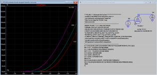
**** EL509_T *************************updated*****************
* Created on 04/28/2022 10:49 using paint_kit.jar 3.1
* www.dmitrynizh.com/tubeparams_image.htm
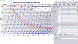
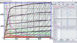
* Plate Curves image file: EL509_TF-T.png
* Data source link:
*----------------------------------------------------------------------------------
.SUBCKT EL509_T 1 2 3 ; Plate Grid Cathode
+ PARAMS: CCG=37P CGP=2.5P CCP=18.5P RGI=2000
+ MU=3.584 KG1=208.25 KP=36.51 KVB=9.38 VCT=-1.883 EX=1.303
* Vp_MAX=500 Ip_MAX=500 Vg_step=10 Vg_start=0 Vg_count=16
* Rp=4000 Vg_ac=55 P_max=40 Vg_qui=-48 Vp_qui=300
* X_MIN=51 Y_MIN=43 X_SIZE=826 Y_SIZE=488 FSZ_X=1296 FSZ_Y=736 XYGrid=false
* showLoadLine=n showIp=y isDHT=n isPP=n isAsymPP=n showDissipLimit=y
* showIg1=n gridLevel2=n isInputSnapped=n
* XYProjections=n harmonicPlot=n dissipPlot=n
*----------------------------------------------------------------------------------
E1 7 0 VALUE={V(1,3)/KP*LOG(1+EXP(KP*(1/MU+(VCT+V(2,3))/SQRT(KVB+V(1,3)*V(1,3)))))}
RE1 7 0 1G ; TO AVOID FLOATING NODES
G1 1 3 VALUE={(PWR(V(7),EX)+PWRS(V(7),EX))/KG1}
RCP 1 3 1G ; TO AVOID FLOATING NODES
C1 2 3 {CCG} ; CATHODE-GRID
C2 2 1 {CGP} ; GRID=PLATE
C3 1 3 {CCP} ; CATHODE-PLATE
D3 5 3 DX ; POSITIVE GRID CURRENT
R1 2 5 {RGI} ; POSITIVE GRID CURRENT
.MODEL DX D(IS=1N RS=1 CJO=10PF TT=1N)
.ENDS
*$Attachments
Last edited:
Hi Ken,Does anyone happen to know if there are any pentode models that model the suppressor grid as an independent control grid? It is not commonly done in the real world and I don't know if there would be any reason to do it in an audio circuit. But I am interested in modeling a signal generator from the 1940's where the screen was used as a plate for the oscillator circuit and the suppressor is used as a control grid between the screen and plate to modulate the plate signal. Cheap radios from the same era did something similar in order to use a pentode in place of a more expensive pentagrid converter. Has anyone ever published spice models for tubes with three or more independent grids?
So far searches have turned up no golden needles in a very large haystack of suppressor grid references that tell me to connect it to the cathode!
Thanks,
Ken
The Suppressor can do much more than slow screen grid electrons and reduce Secondary Emission.
I was given a book in 1952, about how, during WW2, the US military took control of the production of 67.5V and 90V B batteries for use in Walkie Talkies. Experimenters became creative by swapping control, screen and suppressor grids to improve emission and transconductance, allowing Pentodes and Tetrodes to work quite well with +12V plates.
Those tubes led to the 12V automotive tubes of the early 1950s, where car radio output stages were single-ended 100 Watt, Class A Delco 2N174 PNPs. Eventually, the power-hungry Class A car amplifiers were phased out, in favor of relative power-sipping Class AB amps.
Unfortunately, I haven't seen that book in many years.
To show you how far I go back - look at my email address. The Raytheon CK722 was the first US DIY Germanium PNP. When they first came out, in 1952 or 53, I switched from tubes to transistors for a few years.
I broke the Base lead off a CK722, said "What the heck" and cut it open. Inside was a tiny hermetic package. I soldered on a new Base lead and from that time on, I cut all my CK722s open, so they'd fit in my ball point pen regenerative receivers.
60 years later. I found others had had that same experience. Raytheon had repackaged their noisy hearing aid reject transistors and sold them at a premium, to unaware experimenters, $3 each was big money for a teenager. Splendid marketing. Less is More.
Like others, I thought "Someday radios will have hundreds of transistors." Who could have ever dreamed of a micro SD card with a million million, i.e. a trillion or 1E12 transistors?
My ancient, Physics-based LTSpice Intuitive Large Signal Primary* Vacuum Tube Current Simulator should swap grids just fine. I haven't tried swapping yet. I tried it on Tina TI, years ago, but ran into convergence issues.
I just haven't published anything yet and I'm in the middle of two very hot projects. Do you have a particular tube in mind?
Regards,
Ron
*Primary means devoid of Secondary Emission.
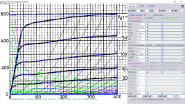
Here's a 2015 sloppy Plate curve of the Remote Cutoff (variable mu) Triode section of the legacy 6AE6. It works just fine with a positive Vg1 or Control Grid.
Attachments
Looking for better PCL200 models both triode and pentode section: https://frank.pocnet.net/sheets/124/p/PCL200.pdf
The ones I have are not good, I think ... :
.SUBCKT PCL200P 1 2 3 4 ; A G2 G1 C (Pentode)
X1 1 2 3 4 PENTODE1 MU=40 EX=2.1 KG1=1000 KG2=4500 KP=150 KVB=17.5 VCT=0.00 RGI=2000 CCG=14.5p CPG1=0.07p CCP=5.8p
.ENDS
.SUBCKT PCL200T 1 2 3 ; P G C (Triode)
X1 1 2 3 TRIODE MU=55 EX=1.225 KG1=600 KP=650 KVB=350 VCT=0.50 RGI=2000 CCG=3.2p CGP=2.5p CCP=4.4p
.ENDS
.subckt PCL200TT p g k
+params: Ku=6.67e-6 Mu=55 Rgk=1e6 Cgk=3.2e-12 Cgp=2.5e-12 Cpk=4.4e-12
gp p k value = {Ku*(pwr(v(p,k)+Mu*v(g,k),1.5)+pwrs(v(p,k)+Mu*v(g,k),1.5))/2}
rgk g x {Rgk}
d1 x k dX
cgk g k {Cgk}
cgp g p {Cgp}
cpk p k {Cpk}
.ends PCL200TT
.subckt PCL200PT p g k
+params: Ku=7.5e-5 Mu=40 Rgk=1e6 Cgk=14.5e-12 Cgp=2.5e-12 Cpk=5.8e-12
gp p k value = {Ku*pwr(uramp(v(p,k)+Mu*v(g,k)),1.5)}
rgk g x {Rgk}
d1 x k dX
cgk g k {Cgk}
cgp g p {Cgp}
cpk p k {Cpk}
.ends PCL200PT
Also wanted: PL508 model : https://frank.pocnet.net/sheets/010/p/PL508.pdf
some say it is similar to russian 6p41s but don't think that's true ...
some say it is similar to russian 6p41s but don't think that's true ...
PCL200 pentode model, try it:
Code:
**** PCL200_P ******************************************
* Created on 05/19/2022 12:03 using paint_kip.jar
* www.dmitrynizh.com/tubeparams_image.htm
* Plate Curves image file: PCL200_P.png
* Data source link: <plate curves URL>
*----------------------------------------------------------------------------------
.SUBCKT PCL200_P P G2 G K ; LTSpice tetrode.asy pinout
* .SUBCKT PCL200_P P G K G2 ; Koren Pentode Pspice pinout
+ PARAMS: MU=55 KG1=209.52 KP=853.19 KVB=12 VCT=2.844E-5 EX=1.302 KG2=460.49 KNEE=9.19 KVC=2.372
+ KLAM=3.482E-7 KLAMG=8.311E-4 KD=5460.22 KC=504.43 KR1=0.04472 KR2=0.01607 KVBG=0.1424 KB1=3.832 KB2=1.955 KB3=0.975 KB4=0.3012 KVBGI=0.6129 KNK=0.1888 KNG=0.01424 KNPL=0.1918 KNSL=0.615 KNPR=0.5624 KNSR=9.37
+ CCG=14.5P CGP=0.07P CCP=5.8P VGOFF=-0.6 IGA=0.00107 IGB=0.252 IGC=12.48 IGEX=1.94
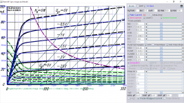
* Vp_MAX=300 Ip_MAX=100 Vg_step=0.5 Vg_start=0 Vg_count=9
* X_MIN=48 Y_MIN=21 X_SIZE=819 Y_SIZE=544 FSZ_X=1296 FSZ_Y=736 XYGrid=false
* Rp=1400 Vg_ac=20 P_max=6 Vg_qui=-2 Vp_qui=300
* showLoadLine=n showIp=y isDHP=n isPP=n isAsymPP=n isUL=n showDissipLimit=y
* showIg1=y isInputSnapped=y addLocalNFB=n
* XYProjections=n harmonicPlot=y dissipPlot=n
* UL=0.43 EG2=200 gridLevel2=y addKink=y isTanhKnee=n advSigmoid=y
*----------------------------------------------------------------------------------
RE1 7 0 1G ; DUMMY SO NODE 7 HAS 2 CONNECTIONS
E1 7 0 VALUE= ; E1 BREAKS UP LONG EQUATION FOR G1.
+{V(G2,K)/KP*LOG(1+EXP((1/MU+(VCT+V(G,K))/SQRT(KVB+V(G2,K)*V(G2,K)))*KP))}
RE2 6 0 1G ; DUMMY SO NODE 6 HAS 2 CONNECTIONS
E2 6 0 VALUE={(PWR(V(7),EX)+PWRS(V(7),EX))} ; Kg1 times KIT current
E4 8 0 VALUE={V(P,K)/KNEE/(KVBGI+V(6)*KVBG)}
E5 81 0 VALUE={PWR(V(8),KB1)}
E6 82 0 VALUE={PWR(V(8),KB2)}
E7 83 0 VALUE={PWR(V(8),KB3)}
E8 9 0 VALUE={PWR(1-EXP(-V(81)*(KC+KR1*V(82))/(KD+KR2*V(83))),KB4)*1.5708}
RE4 8 0 1
RE5 81 0 1
RE6 82 0 1
RE7 83 0 1
RE8 9 0 1
RE21 21 0 1
E21 21 0 VALUE={V(6)/KG1*V(9)} ; Ip with knee but no slope and no kink
RE22 22 0 1 ; E22: kink curr deviation for plate
E22 22 0 VALUE={V(21)*LIMIT(KNK-V(G,K)*KNG,0,0.3)*(-ATAN((V(P,K)-KNPL)/KNSL)+ATAN((V(P,K)-KNPR)/KNSR))}
G1 P K VALUE={V(21)*(1+KLAMG*V(P,K))+KLAM*V(P,K) + V(22)}
G2 G2 K VALUE={V(6)/KG2*(KVC-V(9))/(1+KLAMG*V(P,K)) - V(22)}
RCP P K 1G ; FOR CONVERGENCE
C1 K G {CCG} ; CATHODE-GRID 1
C2 G P {CGP} ; GRID 1-PLATE
C3 K P {CCP} ; CATHODE-PLATE
RE23 G 0 1G
GG G K VALUE={(IGA+IGB/(IGC+V(P,K)))*(MU/KG1)*
+(PWR(V(G,K)-VGOFF,IGEX)+PWRS(V(G,K)-VGOFF,IGEX))}
.ENDS
*$Attachments
PCl200 triode model:
Code:
**** PCL200_T ** Advanced Grid Current **********************************
* Created on 05/19/2022 16:44 using paint_kit.jar 3.1
* www.dmitrynizh.com/tubeparams_image.htm
* Plate Curves image file: PCL200_T.png
* Data source link:
*----------------------------------------------------------------------------------
.SUBCKT PCL200_T 1 2 3 ; Plate Grid Cathode
+ PARAMS: CCG=3.2P  CGP=2.5P CCP=4.4P
+ MU=60.8 KG1=1093.68 KP=418.11 KVB=655.74 VCT=0.7399 EX=1.629
+ VGOFF=-0.6 IGA=0.00093 IGB=0.264 IGC=14.96 IGEX=3.34
* Vp_MAX=400 Ip_MAX=20 Vg_step=1 Vg_start=0 Vg_count=6
* Rp=4000 Vg_ac=55 P_max=1.7 Vg_qui=-48 Vp_qui=300
* X_MIN=53 Y_MIN=10 X_SIZE=800 Y_SIZE=538 FSZ_X=1296 FSZ_Y=736 XYGrid=false
* showLoadLine=n showIp=y isDHT=n isPP=n isAsymPP=n showDissipLimit=y
* showIg1=y gridLevel2=y isInputSnapped=n
* XYProjections=n harmonicPlot=n dissipPlot=n
*----------------------------------------------------------------------------------
E1 7 0 VALUE={V(1,3)/KP*LOG(1+EXP(KP*(1/MU+(VCT+V(2,3))/SQRT(KVB+V(1,3)*V(1,3)))))}
RE1 7 0 1G  ; TO AVOID FLOATING NODES
G1 1 3 VALUE={(PWR(V(7),EX)+PWRS(V(7),EX))/KG1}
RCP 1 3 1G   ; TO AVOID FLOATING NODES
C1 2 3 {CCG} ; CATHODE-GRID
C2 2 1 {CGP} ; GRID=PLATE
C3 1 3 {CCP} ; CATHODE-PLATE
RE2 2 0 1G
EGC 8 0 VALUE={V(2,3)-VGOFF} ; POSITIVE GRID THRESHOLD
GG 2 3 VALUE={(IGA+IGB/(IGC+V(1,3)))*(MU/KG1)*(PWR(V(8),IGEX)+PWRS(V(8),IGEX))}
.ENDS
*$
Attachments
PL508 model to try, there is a triode plot here you can compare:
https://www.diyaudio.com/community/threads/pl508-triode-curves-help.281537/
https://www.diyaudio.com/community/threads/pl508-triode-curves-help.281537/
Code:
**** PL508 ******************************************
* Created on 05/19/2022 20:55 using paint_kip.jar
* www.dmitrynizh.com/tubeparams_image.htm
* Plate Curves image file: PL508.png
* Data source link: <plate curves URL>
*----------------------------------------------------------------------------------
.SUBCKT PL508 P G2 G K ; LTSpice tetrode.asy pinout
* .SUBCKT PL508 P G K G2 ; Koren Pentode Pspice pinout
+ PARAMS: MU=8.88 KG1=1019.84 KP=32 KVB=1905.87 VCT=-1.65 EX=1.624 KG2=1302.84 KNEE=8.7 KVC=1.77
+ KLAM=2E-6 KLAMG=3.188E-7 KD=0.05733 KC=0.1903 KR1=0.004858 KR2=0.02143 KVBG=0.01551 KB1=3.172 KB2=1.668 KB3=2.93 KB4=0.403 KVBGI=0.002247 KNK=0.07168 KNG=0.002825 KNPL=2.179E-8 KNSL=1.151E-4 KNPR=198.38 KNSR=119.32
+ CCG=1P CGP=1.6P CCP=1P VGOFF=-0.6 IGA=0.001 IGB=0.3 IGC=8 IGEX=2
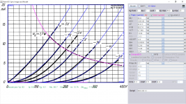
* Vp_MAX=400 Ip_MAX=600 Vg_step=5 Vg_start=0 Vg_count=13
* X_MIN=67 Y_MIN=77 X_SIZE=743 Y_SIZE=554 FSZ_X=1296 FSZ_Y=736 XYGrid=false
* Rp=1400 Vg_ac=20 P_max=12 Vg_qui=-30 Vp_qui=300
* showLoadLine=n showIp=y isDHP=n isPP=n isAsymPP=n isUL=n showDissipLimit=y
* showIg1=y isInputSnapped=y addLocalNFB=n
* XYProjections=n harmonicPlot=y dissipPlot=n
* UL=0.43 EG2=250 gridLevel2=y addKink=y isTanhKnee=n advSigmoid=y
*----------------------------------------------------------------------------------
RE1 7 0 1G ; DUMMY SO NODE 7 HAS 2 CONNECTIONS
E1 7 0 VALUE= ; E1 BREAKS UP LONG EQUATION FOR G1.
+{V(G2,K)/KP*LOG(1+EXP((1/MU+(VCT+V(G,K))/SQRT(KVB+V(G2,K)*V(G2,K)))*KP))}
RE2 6 0 1G ; DUMMY SO NODE 6 HAS 2 CONNECTIONS
E2 6 0 VALUE={(PWR(V(7),EX)+PWRS(V(7),EX))} ; Kg1 times KIT current
E4 8 0 VALUE={V(P,K)/KNEE/(KVBGI+V(6)*KVBG)}
E5 81 0 VALUE={PWR(V(8),KB1)}
E6 82 0 VALUE={PWR(V(8),KB2)}
E7 83 0 VALUE={PWR(V(8),KB3)}
E8 9 0 VALUE={PWR(1-EXP(-V(81)*(KC+KR1*V(82))/(KD+KR2*V(83))),KB4)*1.5708}
RE4 8 0 1
RE5 81 0 1
RE6 82 0 1
RE7 83 0 1
RE8 9 0 1
RE21 21 0 1
E21 21 0 VALUE={V(6)/KG1*V(9)} ; Ip with knee but no slope and no kink
RE22 22 0 1 ; E22: kink curr deviation for plate
E22 22 0 VALUE={V(21)*LIMIT(KNK-V(G,K)*KNG,0,0.3)*(-ATAN((V(P,K)-KNPL)/KNSL)+ATAN((V(P,K)-KNPR)/KNSR))}
G1 P K VALUE={V(21)*(1+KLAMG*V(P,K))+KLAM*V(P,K) + V(22)}
G2 G2 K VALUE={V(6)/KG2*(KVC-V(9))/(1+KLAMG*V(P,K)) - V(22)}
RCP P K 1G ; FOR CONVERGENCE
C1 K G {CCG} ; CATHODE-GRID 1
C2 G P {CGP} ; GRID 1-PLATE
C3 K P {CCP} ; CATHODE-PLATE
RE23 G 0 1G
GG G K VALUE={(IGA+IGB/(IGC+V(P,K)))*(MU/KG1)*
+(PWR(V(G,K)-VGOFF,IGEX)+PWRS(V(G,K)-VGOFF,IGEX))}
.ENDS
*$Attachments
https://www.diyaudio.com/community/threads/pl508-triode-curves-help.281537/
Speicific PL508 triode model:
Speicific PL508 triode model:
Code:
**** PL508_T ** Advanced Grid Current **********************************
* Created on 05/19/2022 23:13 using paint_kit.jar 3.1
* www.dmitrynizh.com/tubeparams_image.htm
* Plate Curves image file: PL508-T.png
* Data source link:
*----------------------------------------------------------------------------------
.SUBCKT TRIODE_PL508_T 1 2 3 ; Plate Grid Cathode
+ PARAMS: CCG=3P  CGP=1.4P CCP=1.9P
+ MU=11.58 KG1=128.86 KP=33.05 KVB=173.95 VCT=-1.684 EX=1.062
+ VGOFF=-0.6 IGA=0.001 IGB=0.3 IGC=8 IGEX=2
* Vp_MAX=400 Ip_MAX=150 Vg_step=4 Vg_start=0 Vg_count=16
* Rp=4000 Vg_ac=55 P_max=14 Vg_qui=-48 Vp_qui=300
* X_MIN=40 Y_MIN=40 X_SIZE=811 Y_SIZE=541 FSZ_X=1296 FSZ_Y=736 XYGrid=false
* showLoadLine=n showIp=y isDHT=n isPP=n isAsymPP=n showDissipLimit=y
* showIg1=y gridLevel2=y isInputSnapped=n
* XYProjections=n harmonicPlot=n dissipPlot=n
*----------------------------------------------------------------------------------
E1 7 0 VALUE={V(1,3)/KP*LOG(1+EXP(KP*(1/MU+(VCT+V(2,3))/SQRT(KVB+V(1,3)*V(1,3)))))}
RE1 7 0 1G  ; TO AVOID FLOATING NODES
G1 1 3 VALUE={(PWR(V(7),EX)+PWRS(V(7),EX))/KG1}
RCP 1 3 1G   ; TO AVOID FLOATING NODES
C1 2 3 {CCG} ; CATHODE-GRID
C2 2 1 {CGP} ; GRID=PLATE
C3 1 3 {CCP} ; CATHODE-PLATE
RE2 2 0 1G
EGC 8 0 VALUE={V(2,3)-VGOFF} ; POSITIVE GRID THRESHOLD
GG 2 3 VALUE={(IGA+IGB/(IGC+V(1,3)))*(MU/KG1)*(PWR(V(8),IGEX)+PWRS(V(8),IGEX))}
.ENDS
*$
Attachments
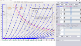
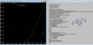
Many, many thank you s ...PCL200 pentode model, try it:
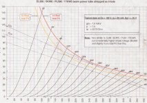
what a transfer curve ... !
I do get strange results with the PL508 tetrode, though ...PL508 model to try
Code:**** PL508 ****************************************** * Created on 05/19/2022 20:55 using paint_kip.jar * www.dmitrynizh.com/tubeparams_image.htm * Plate Curves image file: PL508.png * Data source link: <plate curves URL> *---------------------------------------------------------------------------------- .SUBCKT PL508 P G2 G K ; LTSpice tetrode.asy pinout .ENDS *$
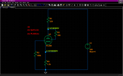
I traced it down using a very simple basic grounded cathode circuit (see ZIP file):
In my good old LTSpice IV the DC OP point analysis runs some length in Damped Pseudo-Transient analysis but finally comes up with what may be a reasonable result.
In LTSpice XVII the DC OP point analysis fails right away showing negative gigavolts ...
When I do the same circuit with Ayjumi 6P41S model no problem ...
Attachments
Try to add the follower options and using Alternate resolver (Tools->Control Panel-> Spice Solver Alternate):
.option noopiter
.options GminSteps=0
.options SrcSteps=1000
This will start source stepping with srcstepmethod=1000, increase as will until it' successful. This condition is best for model created by Paint Tools some models are more complex than others so you need to set the favorable options and alternate solver.
Attachments
Hi Sorento,I do get strange results with the PL508 tetrode, though ...
I traced it down using a very simple basic grounded cathode circuit (see ZIP file):
In my good old LTSpice IV the DC OP point analysis runs some length in Damped Pseudo-Transient analysis but finally comes up with what may be a reasonable result.
In LTSpice XVII the DC OP point analysis fails right away showing negative gigavolts ...
When I do the same circuit with Ayjumi 6P41S model no problem ...
I do a lot of nonlinear stuff, like log/antilog circuits and vacuum tube simulations - my very first and lasting experience was 1st generation (1975) CT scanner photomultiplier front ends. The preamps were logarithmic (because tissue attenuation is exponential with thickness) and I was addicted for life.
I've had frequent nonlinear convergence issues with LTSpice from its inception up to LTSpice IV. The fixes were crap shoots.
(you have to understand - I was using log loops, nested within exponential loops, going back and forth, between log and linear space).
LTSpice VIII was unbearable, so I did three things, 1) removed LTSpice VIII from all my Windows laptops, 2) reinstalled LTSpice IV and 3) started using externally bounded Voltage Controlled Current Sources instead of even idealized op amps. A bit more complex, but they stopped most convergence problems. I just don't know what's inside LT's op amp macromodels.
TI Tina was as bad, convergence-wise, as LTSpice VIII.
When I was with National Semiconductor, many of the Applications Engineers liked LTSpice.
Last edited:
Thanks,Try to add the follower options and using Alternate resolver (Tools->Control Panel-> Spice Solver Alternate):
.option noopiter
.options GminSteps=0
.options SrcSteps=1000
This will start source stepping with srcstepmethod=1000, increase as will until it' successful. This condition is best for model created by Paint Tools some models are more complex than others so you need to set the favorable options and alternate solver.
the SrcSteps option alone seems to do the trick.
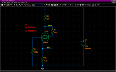
but we also seem to have an issue with Ig2 now ...
the datasheet gives a characteristic operating point Va = Vg2 = 190V / Vg1 = -17V / Ia = 60mA / Ig2 = 5mA
when I sim that, I get Ia=43mA (lower) and Ig2=15mA ( ! three times the datasheet number !)
my intended application involves the PL508 or 6P41S in a dual drive (both g1 and g2 driven by a PCL200),
so g2 current is of the essence ...
Attachments
@ronck722
Maybe we shouldn't be too harsh with LTSpice.
For once it is free ...
And then historically it started out as "Switcher Cad", primarily intended to cut down execution time for SMPS sims.
And it still does that quite well compared to more traditional implementations of Spice.
To achieve this it seems to take a couple of shortcuts - which shows once in a while with complex analogue stuff ...
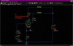
New screen model: Va = Vg2 = 190V / Vg1 = -17V / Ia = 55mA / Ig2 = 5.8mAthe datasheet gives a characteristic operating point Va = Vg2 = 190V / Vg1 = -17V / Ia = 60mA / Ig2 = 5mA
Try, I remodeled screen current (based on the above), as no other references are found further alignment prove difficult.
Code:
**** PL508 *******************************2 good***********
* Created on 05/21/2022 13:55 using paint_kip.jar
* www.dmitrynizh.com/tubeparams_image.htm
* Plate Curves image file: PL508.png
* Data source link: <plate curves URL>
*----------------------------------------------------------------------------------
.SUBCKT PL508 P G2 G K ; LTSpice tetrode.asy pinout
* .SUBCKT PL508 P G K G2 ; Koren Pentode Pspice pinout
+ PARAMS: MU=8.88 KG1=1167.52 KP=28.8 KVB=1905.87 VCT=-0.8137 EX=1.592 KG2=2970.48 KNEE=8.7 KVC=1.575
+ KLAM=6.25E-9 KLAMG=2.742E-4  KD=0.03726 KC=0.099 KR1=0.004858 KR2=0.02143 KVBG=0.01551 KB1=3.172 KB2=1.668 KB3=2.93 KB4=0.403 KVBGI=0.002247 KNK=0.02024 KNG=0.004633 KNPL=2.31E-8 KNSL=1.22E-4 KNPR=125.82 KNSR=103.49
+ CCG=1P CGP=1.6P CCP=1P VGOFF=-0.6 IGA=0.001 IGB=0.3 IGC=8 IGEX=2
* Vp_MAX=400 Ip_MAX=600 Vg_step=5 Vg_start=0 Vg_count=13
* X_MIN=68 Y_MIN=22 X_SIZE=782 Y_SIZE=586 FSZ_X=1296 FSZ_Y=736 XYGrid=false
* Rp=1400 Vg_ac=20 P_max=12 Vg_qui=-30 Vp_qui=300
* showLoadLine=n showIp=y isDHP=n isPP=n isAsymPP=n isUL=n showDissipLimit=y
* showIg1=y isInputSnapped=y addLocalNFB=n
* XYProjections=n harmonicPlot=y dissipPlot=n
* UL=0.43 EG2=250 gridLevel2=y addKink=y isTanhKnee=n advSigmoid=y
*----------------------------------------------------------------------------------
RE1  7 0  1G    ; DUMMY SO NODE 7 HAS 2 CONNECTIONS
E1   7 0  VALUE=  ; E1 BREAKS UP LONG EQUATION FOR G1.
+{V(G2,K)/KP*LOG(1+EXP((1/MU+(VCT+V(G,K))/SQRT(KVB+V(G2,K)*V(G2,K)))*KP))}
RE2  6 0  1G    ; DUMMY SO NODE 6 HAS 2 CONNECTIONS
E2  6 0  VALUE={(PWR(V(7),EX)+PWRS(V(7),EX))} ; Kg1 times KIT current
E4   8 0  VALUE={V(P,K)/KNEE/(KVBGI+V(6)*KVBG)}
E5  81 0  VALUE={PWR(V(8),KB1)}
E6  82 0  VALUE={PWR(V(8),KB2)}
E7  83 0  VALUE={PWR(V(8),KB3)}
E8   9 0  VALUE={PWR(1-EXP(-V(81)*(KC+KR1*V(82))/(KD+KR2*V(83))),KB4)*1.5708}
RE4  8 0  1
RE5 81 0  1
RE6 82 0  1
RE7 83 0  1
RE8  9 0  1
RE21 21 0 1
E21  21 0 VALUE={V(6)/KG1*V(9)} ; Ip with knee but no slope and no kink
RE22 22 0 1 ; E22: kink curr deviation for plate
E22  22 0 VALUE={V(21)*LIMIT(KNK-V(G,K)*KNG,0,0.3)*(-ATAN((V(P,K)-KNPL)/KNSL)+ATAN((V(P,K)-KNPR)/KNSR))}
G1   P K  VALUE={V(21)*(1+KLAMG*V(P,K))+KLAM*V(P,K) + V(22)}
G2   G2 K  VALUE={V(6)/KG2*(KVC-V(9))/(1+KLAMG*V(P,K)) - V(22)}
RCP  P K  1G     ; FOR CONVERGENCE
C1   K G  {CCG}  ; CATHODE-GRID 1
C2   G P  {CGP}  ; GRID 1-PLATE
C3   K P  {CCP}  ; CATHODE-PLATE
RE23 G 0 1G
GG G K VALUE={(IGA+IGB/(IGC+V(P,K)))*(MU/KG1)*
+(PWR(V(G,K)-VGOFF,IGEX)+PWRS(V(G,K)-VGOFF,IGEX))}
.ENDS
*$
Attachments
PL508 Siemens, brand new out of box:concerning the PL508, looks good for now;
I think I can make some measurements of Ig2 vs Va / Vg2 to get a few more data points ...
Va / Vg2 / Ia / Ig2 in that order, Vg1 = -18V (just two used 9V batteries in series)
190V / 190V / 61mA / 4.8mA
200V / 200V / 72mA / 5.7mA
210V / 210V / 91mA / 7.2mA
220V / 220V / 107mA / 8.6mA
250V / 200V / 76mA / 4.3mA
275V / 195V / 70mA / 3.4mA
300V / 130V / 39mA / 1.3mA
- Home
- Amplifiers
- Tubes / Valves
- Vacuum Tube SPICE Models