https://www.google.com/url?sa=t&rct...tigation.pdf&usg=AOvVaw1FRp8lt5bSYNUPfurWiUIe
There are a number of Pentode UL Triode curve in this article you can use as reference if you try to plot and compare using our model.
There are a number of Pentode UL Triode curve in this article you can use as reference if you try to plot and compare using our model.
Attachments
Last edited:
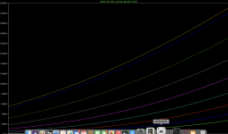
Yes, you can detect U1 for SE operation if you modify the operating point as follows:
.param Va=0
.dc v3 0 450 1 v1 36 -36 -9
Keep the rest unchanged, this gives horizontal scale 0-450V for the SE curve plot.
Koonw
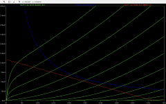
I may be going awry somewhere. I was hoping to see more classical UL type curves
Attachments
Rather than asking to modify PP model, use this model which is intended for SE amp. You can plot any other tube by changing the tube name say 6bq5 (EL84), you should have 6bq5 model on display directive or as statement ".lib 6bq5.inc" where model files "6bq5.inc" is located in lib directory of LTSpice.
You change .dc sweep range to suit your plot. ".dc" function can be modified directly or click on "Simulate" -> Edit Simulation Cmd" -> DC SWEEP, then change the "1st Source" which is anode range and "2nd Source" which is the grid 1 range to suit. You can also change ".param UL=0.43" if you want to plot other curve, so "param UL=0.33" plot curve for 33% UL tap.
You change .dc sweep range to suit your plot. ".dc" function can be modified directly or click on "Simulate" -> Edit Simulation Cmd" -> DC SWEEP, then change the "1st Source" which is anode range and "2nd Source" which is the grid 1 range to suit. You can also change ".param UL=0.43" if you want to plot other curve, so "param UL=0.33" plot curve for 33% UL tap.
Attachments
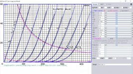
Thanks for your patience and apologies I have a lot of understanding to catchup on especially on UL. I substituted the 6BQ5 for a try out. Further work to see which load line gives optimum results.
Attachments
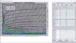
Here 6V6GT GE model, original curve has triode, grid#1 and grid#2 current curve:
Code:
**** 6V6GT ******************************************
* Created on 08/20/2021 15:48 using paint_kip.jar
* [url=http://www.dmitrynizh.com/tubeparams_image.htm]Model Paint Tools: Trace Tube Parameters over Plate Curves, Interactively[/url]
* Plate Curves image file: 6v6gt.png
* Data source link: <plate curves URL>
*----------------------------------------------------------------------------------
.SUBCKT 6V6GT P G2 G K ; LTSpice tetrode.asy pinout
* .SUBCKT 6V6GT P G K G2 ; Koren Pentode Pspice pinout
+ PARAMS: MU=10.7 KG1=1676.38 KP=46.44 KVB=1412.81 VCT=-0.0399 EX=1.306 KG2=2635.52 KNEE=9.75 KVC=1.67
+ KLAM=1.5E-9 KLAMG=1.35E-4  KD=0.02767 KC=0.2692 KR1=1.112E-5 KR2=0.06456 KVBG=0.01817 KB1=1.299 KB2=3.194 KB3=1.125E-5 KB4=0.98 KVBGI=3.975E-6 KNK=0.1559 KNG=0.00951 KNPL=1.145E-6 KNSL=3.87E-4 KNPR=0.4664 KNSR=84.99
+ CCG=0.7P CGP=9P CCP=7.5P VGOFF=-3.6 IGA=8.688E-5 IGB=0.007008 IGC=15 IGEX=3.236
* Vp_MAX=500 Ip_MAX=140 Vg_step=5 Vg_start=0 Vg_count=14
* X_MIN=37 Y_MIN=25 X_SIZE=731 Y_SIZE=516 FSZ_X=1288 FSZ_Y=723 XYGrid=false
* Rp=1400 Vg_ac=20 P_max=12 Vg_qui=-32.5 Vp_qui=300
* showLoadLine=n showIp=y isDHP=n isPP=n isAsymPP=n isUL=n showDissipLimit=y
* showIg1=y isInputSnapped=y addLocalNFB=n
* XYProjections=n harmonicPlot=y dissipPlot=n
* UL=0.43 EG2=250 gridLevel2=y addKink=y isTanhKnee=n advSigmoid=y
*----------------------------------------------------------------------------------
RE1  7 0  1G    ; DUMMY SO NODE 7 HAS 2 CONNECTIONS
E1   7 0  VALUE=  ; E1 BREAKS UP LONG EQUATION FOR G1.
+{V(G2,K)/KP*LOG(1+EXP((1/MU+(VCT+V(G,K))/SQRT(KVB+V(G2,K)*V(G2,K)))*KP))}
RE2  6 0  1G    ; DUMMY SO NODE 6 HAS 2 CONNECTIONS
E2  6 0  VALUE={(PWR(V(7),EX)+PWRS(V(7),EX))} ; Kg1 times KIT current
E4   8 0  VALUE={V(P,K)/KNEE/(KVBGI+V(6)*KVBG)}
E5  81 0  VALUE={PWR(V(8),KB1)}
E6  82 0  VALUE={PWR(V(8),KB2)}
E7  83 0  VALUE={PWR(V(8),KB3)}
E8   9 0  VALUE={PWR(1-EXP(-V(81)*(KC+KR1*V(82))/(KD+KR2*V(83))),KB4)*1.5708}
RE4  8 0  1
RE5 81 0  1
RE6 82 0  1
RE7 83 0  1
RE8  9 0  1
RE21 21 0 1
E21  21 0 VALUE={V(6)/KG1*V(9)} ; Ip with knee but no slope and no kink
RE22 22 0 1 ; E22: kink curr deviation for plate
E22  22 0 VALUE={V(21)*LIMIT(KNK-V(G,K)*KNG,0,0.3)*(-ATAN((V(P,K)-KNPL)/KNSL)+ATAN((V(P,K)-KNPR)/KNSR))}
G1   P K  VALUE={V(21)*(1+KLAMG*V(P,K))+KLAM*V(P,K) + V(22)}
G2   G2 K  VALUE={V(6)/KG2*(KVC-V(9))/(1+KLAMG*V(P,K)) - V(22)}
RCP  P K  1G     ; FOR CONVERGENCE
C1   K G  {CCG}  ; CATHODE-GRID 1
C2   G P  {CGP}  ; GRID 1-PLATE
C3   K P  {CCP}  ; CATHODE-PLATE
RE23 G 0 1G
GG G K VALUE={(IGA+IGB/(IGC+V(P,K)))*(MU/KG1)*
+(PWR(V(G,K)-VGOFF,IGEX)+PWRS(V(G,K)-VGOFF,IGEX))}
.ENDS
*$
Attachments
I can't find this tube anywhere, do you have the original tube data curve?Is available subminiature 8185 spice model?
Ok I find it
https://www.google.com/url?sa=t&rct...ia-SSFGT.pdf&usg=AOvVaw0Elj_4IpVhxThUeWnA38ou
8185 model, try it:
Code:
**** 8185 ** Advanced Grid Current **********************************
* Created on 08/22/2021 11:30 using paint_kit.jar 3.1
* [URL="http://www.dmitrynizh.com/tubeparams_image.htm"]www.dmitrynizh.com/tubeparams_image.htm[/URL]
* Plate Curves image file: 8185.png
* Data source link:
*----------------------------------------------------------------------------------
.SUBCKT 8185 1 2 3 ; Plate Grid Cathode
+ PARAMS: CCG=6P  CGP=5P CCP=0.3P
+ MU=47.04 KG1=84.83 KP=376 KVB=282 VCT=0.1888 EX=1.21
+ VGOFF=-0.6 IGA=6.25E-6 IGB=0.189 IGC=11.76 IGEX=1.38
* Vp_MAX=450 Ip_MAX=60 Vg_step=1 Vg_start=0 Vg_count=9
* Rp=4000 Vg_ac=55 P_max=4.25 Vg_qui=-48 Vp_qui=300
* X_MIN=37 Y_MIN=16 X_SIZE=841 Y_SIZE=565 FSZ_X=1296 FSZ_Y=736 XYGrid=true
* showLoadLine=n showIp=y isDHT=n isPP=n isAsymPP=n showDissipLimit=y
* showIg1=y gridLevel2=y isInputSnapped=n
* XYProjections=n harmonicPlot=n dissipPlot=n
*----------------------------------------------------------------------------------
E1 7 0 VALUE={V(1,3)/KP*LOG(1+EXP(KP*(1/MU+(VCT+V(2,3))/SQRT(KVB+V(1,3)*V(1,3)))))}
RE1 7 0 1G  ; TO AVOID FLOATING NODES
G1 1 3 VALUE={(PWR(V(7),EX)+PWRS(V(7),EX))/KG1}
RCP 1 3 1G   ; TO AVOID FLOATING NODES
C1 2 3 {CCG} ; CATHODE-GRID
C2 2 1 {CGP} ; GRID=PLATE
C3 1 3 {CCP} ; CATHODE-PLATE
RE2 2 0 1G
EGC 8 0 VALUE={V(2,3)-VGOFF} ; POSITIVE GRID THRESHOLD
GG 2 3 VALUE={(IGA+IGB/(IGC+V(1,3)))*(MU/KG1)*(PWR(V(8),IGEX)+PWRS(V(8),IGEX))}
.ENDS
*$
Attachments
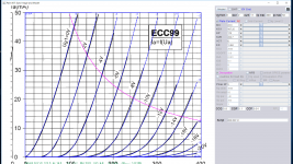
ECC99 JJ model:
Code:
**** ECC99 ** Advanced Grid Current **********************************
* Created on 08/22/2021 00:55 using paint_kit.jar 3.1
* [url=http://www.dmitrynizh.com/tubeparams_image.htm]Model Paint Tools: Trace Tube Parameters over Plate Curves, Interactively[/url]
* Plate Curves image file: ecc99.png
* Data source link:
*----------------------------------------------------------------------------------
.SUBCKT ECC99 1 2 3 ; Plate Grid Cathode
+ PARAMS: CCG=5.8P  CGP=5.1P CCP=0.91P
+ MU=23.6 KG1=437.25 KP=170 KVB=2.247 VCT=0 EX=1.484
+ VGOFF=-0.6 IGA=5.6E-4 IGB=0.141 IGC=11.28 IGEX=2
* Vp_MAX=400 Ip_MAX=50 Vg_step=2 Vg_start=0 Vg_count=11
* Rp=4000 Vg_ac=55 P_max=5 Vg_qui=-48 Vp_qui=300
* X_MIN=76 Y_MIN=22 X_SIZE=737 Y_SIZE=610 FSZ_X=1296 FSZ_Y=736 XYGrid=false
* showLoadLine=n showIp=y isDHT=n isPP=n isAsymPP=n showDissipLimit=y
* showIg1=y gridLevel2=y isInputSnapped=n
* XYProjections=n harmonicPlot=n dissipPlot=n
*----------------------------------------------------------------------------------
E1 7 0 VALUE={V(1,3)/KP*LOG(1+EXP(KP*(1/MU+(VCT+V(2,3))/SQRT(KVB+V(1,3)*V(1,3)))))}
RE1 7 0 1G  ; TO AVOID FLOATING NODES
G1 1 3 VALUE={(PWR(V(7),EX)+PWRS(V(7),EX))/KG1}
RCP 1 3 1G   ; TO AVOID FLOATING NODES
C1 2 3 {CCG} ; CATHODE-GRID
C2 2 1 {CGP} ; GRID=PLATE
C3 1 3 {CCP} ; CATHODE-PLATE
RE2 2 0 1G
EGC 8 0 VALUE={V(2,3)-VGOFF} ; POSITIVE GRID THRESHOLD
GG 2 3 VALUE={(IGA+IGB/(IGC+V(1,3)))*(MU/KG1)*(PWR(V(8),IGEX)+PWRS(V(8),IGEX))}
.ENDS
*$
Attachments
Hello,
Please, I have a question for the 2P29L model bellow:
** 2P29L TRIODE ************************************************************
* Created on Fri Jun 15 19:29:17 BST 2012 using tube.model.finder.PaintKIT
* model URL:Bartola® Valves – All about electronic valves and hi-fi
*--------------------------------------------------
.SUBCKT 2P29L-T_AM 1 2 3 ; A G K
+ PARAMS: CCG=6P CGP=8P CCP=4P RGI=2000
+ MU=9.1 EX=1.4 KG1=2445 KP=140 KVB=21 VCT=-0.46 ; Vp_MAX=200.0 Ip_MAX=0.08 Vg_step=2.0
*--------------------------------------------------
E1 7 0 VALUE={V(1,3)/KP*LOG(1+EXP(KP*(1/MU+(VCT+V(2,3))/SQRT(KVB+V(1,3)*V(1,3)))))}
RE1 7 0 1G
G1 1 3 VALUE={(PWR(V(7),EX)+PWRS(V(7),EX))/KG1}
RCP 1 3 1G ; TO AVOID FLOATING NODES
C1 2 3 {CCG} ; CATHODE-GRID
C2 2 1 {CGP} ; GRID=PLATE
C3 1 3 {CCP} ; CATHODE-PLATE
D3 5 3 DX ; FOR GRID CURRENT
R1 2 5 {RGI} ; FOR GRID CURRENT
.MODEL DX D(IS=1N RS=1 CJO=10PF TT=1N)
.ENDS
*$
When I run it, I have the following error:
"Port(pin) count mismatch between the definition of subcircuit "2P29" and instance "xU1" ...".
For xU1 I have used the standard Triode model.
Do you know what is wrong ?
Thank you in advance.
Pierre
You'll have to use Triode symbol instead of Tetrode/Pentode as this is the Triode model of 2P29L which is a Pentode. The tube name should be "2P29L-T_AM" unless you change it in model file. else it may point to another model with different pins layout.
https://i1.wp.com/www.bartola.co.uk/valves/wp-content/uploads/2016/06/2P29L-Preamp.png
https://i1.wp.com/www.bartola.co.uk/valves/wp-content/uploads/2016/06/2P29L-Preamp.png
Last edited:
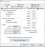
If you have problem running any of my model incomplete or slow, try to configure the Control Panel of LTSpice as attached it works like magic: fast and complete. If this works for any other model other than Paint, let's know thanks.
Matrix Compiler > pseudo code or off
Matrix Compiler > pseudo code or off
Attachments
Sorry I cannot load, with this error "Aborting: unknown schematic syntax: V"In that case try to run this file from me to see any issue.
??
I have compared with old ones of mine, it seams same regarding the syntax. I don't understand.

Now it's ok.
Two errors from me
1/ Into the definition of the triode:
SpiceModel = 2P29L_T_AM
Value=2P29L_T_AM
and
Directive : .lib "2P29L_T.txt"
2/ Into the file description I had
G1 1 3 VALUE={(PWR(V(7),EX)+PWRS(V(7),EX))/KG1}
But KG1 was defined elsewhere into the file as KG and not KG1, so modified the description file.
Hi Koonw, thank you for your support.
Rgds,
Pierre
- Home
- Amplifiers
- Tubes / Valves
- Vacuum Tube SPICE Models