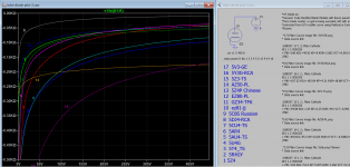
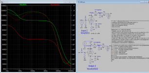
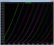
Another one may come handy.After gaining some speeds in simulation, I am finally able to plot something for sharing, hope you enjoy looking.
Attachments
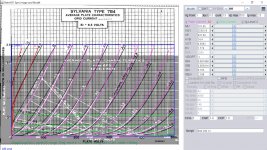
You should explain amplification factor MU in diode (or vacuum diode).
Amplification factor is difference between output and input signal (voltage, current, photoelectrons in photodiodes .....)
Mu is only name of the parameter- could be just one of the parameter for curve fitting, could be changed to any name you like. Like Koren model, it parameters are not based on actual theory but a mean to achieve target result when incorporate in expression, what name would be suggest in this single step curve? Diode gain or? Ya, there is such a thing call diode gain. For most curves I try to keep it as 100.
Last edited:
ha, Mu just change the slope of curve while pin at 0,0. the curve shows that what happened when Mu change to 50 from 100For most curves I try to keep it as 100.
Just like ECC83 gain.
OK, whatever you want.
Attachments
When jazbo8 be back, maybee.
He hasn't posted since 2019
I invite you to watch this Youtube video:Another one may come handy.
"SS, 5U4, 5V4, 5AR4, 5V3 & 5Y3 Rectifiers Compared In 75 Watt Vacuum Tube Audio Amplifier"
Attachments
Last edited:
That's a very useful video. I have compared the 5U4G with the 5V3, and got approximately the same result. I'm using the 5V3 because my filter input capacitance is 40μF.I invite you to watch this Youtube video:
"SS, 5U4, 5V4, 5AR4, 5V3 & 5Y3 Rectifiers Compared In 75 Watt Vacuum Tube Audio Amplifier"
Has anyone verified the 6SF5 model?
I've drawn a circuit in LTSpice and the DC parameters are way off from the point I picked from the datasheet curves. It almost looks like something is off by a factor of 2.
Just to be sure I have the correct model, this is what I copied from the Spice model thread:
*
* Generic triode model: 6SF5_AN
* Copyright 2003--2008 by Ayumi Nakabayashi, All rights reserved.
* Version 3.10, Generated on Sat Dec 13 18:55:08 2014
* Plate
* | Grid
* | | Cathode
* | | |
.SUBCKT 6SF5_AN A G K
BGG GG 0 V=V(G,K)+0.99999997
BM1 M1 0 V=(0.031634481*(URAMP(V(A,K))+1e-10))**-0.46975888
BM2 M2 0 V=(0.76151452*(URAMP(V(GG)+URAMP(V(A,K))/7.5387827)+1e-10))**1.9697589
BP P 0 V=0.00039029593*(URAMP(V(GG)+URAMP(V(A,K))/9.8997228)+1e-10)**1.5
BIK IK 0 V=U(V(GG))*V(P)+(1-U(V(GG)))*0.00022622154*V(M1)*V(M2)
BIG IG 0 V=0.00019514796*URAMP(V(G,K))**1.5*(URAMP(V(G,K))/(URAMP(V(A,K))+URAMP(V(G,K)))*1.2+0.4)
BIAK A K I=URAMP(V(IK,IG)-URAMP(V(IK,IG)-(0.00025575454*URAMP(V(A,K))**1.5)))+1e-10*V(A,K)
BIGK G K I=V(IG)
* CAPS
CGA G A 2.4p
CGK G K 4p
CAK A K 3.6p
.ENDS
Thanks Adrian. I now see the correction in #1674 also.
And related to the same issue, I see there is a separate and different model for 6F5, which is the same tube except for the top cap. Anyone know why?
Most probably someone modeled another one based on actual tracer plot instead of original datasheet of same tubes or later version.
Read 6C33C SPICE MOdel and Autoponte Circlotron
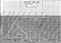
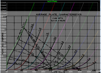
Some remodeled it because they want to include grid current model and positive grid bias region, esp DHT A2 amp designs, even the origin curve do not mention. You can judge by comparing the final amp with the model to see the differences and adjustment thereby refined the model. 7B4 has curve plot into positive region and some grid current data otherwise they're quite close.
Attachments
Last edited:
There are some other models in Ayumi zip model are out, since they are being copied from Ayumi's website, as far as I can see not all are verified at the time of copied.
Here is my 6f5 model included grid current model using 7b4 as a hint:
Here is my 6f5 model included grid current model using 7b4 as a hint:
Code:
**** 6F5 ** Advanced Grid Current **********************************
* Created on 06/18/2020 05:58 using paint_kit.jar 3.1
* [URL="http://www.dmitrynizh.com/tubeparams_image.htm"]www.dmitrynizh.com/tubeparams_image.htm[/URL]
* Plate Curves image file: 6f5.png
* Data source link:
*----------------------------------------------------------------------------------
.SUBCKT 6F5 1 2 3 ; Plate Grid Cathode
+ PARAMS: CCG=3P  CGP=1.4P CCP=1.9P
+ MU=101.65 KG1=2530.18 KP=931.84 KVB=14.4 VCT=0.5692 EX=1.774
+ VGOFF=-1 IGA=0.001498 IGB=0.005414 IGC=8.755 IGEX=2.198
* Vp_MAX=500 Ip_MAX=2.5 Vg_step=0.5 Vg_start=1 Vg_count=13
* Rp=4000 Vg_ac=55 P_max=40 Vg_qui=-48 Vp_qui=300
* X_MIN=56 Y_MIN=189 X_SIZE=779 Y_SIZE=441 FSZ_X=1296 FSZ_Y=736 XYGrid=false
* showLoadLine=n showIp=y isDHT=n isPP=n isAsymPP=n showDissipLimit=n
* showIg1=y gridLevel2=y isInputSnapped=n
* XYProjections=n harmonicPlot=n dissipPlot=n
*----------------------------------------------------------------------------------
E1 7 0 VALUE={V(1,3)/KP*LOG(1+EXP(KP*(1/MU+(VCT+V(2,3))/SQRT(KVB+V(1,3)*V(1,3)))))}
RE1 7 0 1G  ; TO AVOID FLOATING NODES
G1 1 3 VALUE={(PWR(V(7),EX)+PWRS(V(7),EX))/KG1}
RCP 1 3 1G   ; TO AVOID FLOATING NODES
C1 2 3 {CCG} ; CATHODE-GRID
C2 2 1 {CGP} ; GRID=PLATE
C3 1 3 {CCP} ; CATHODE-PLATE
RE2 2 0 1G
EGC 8 0 VALUE={V(2,3)-VGOFF} ; POSITIVE GRID THRESHOLD
GG 2 3 VALUE={(IGA+IGB/(IGC+V(1,3)))*(MU/KG1)*(PWR(V(8),IGEX)+PWRS(V(8),IGEX))}
.ENDS
*$
Attachments
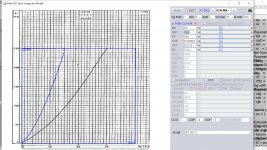
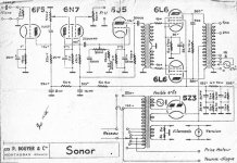
Here is one 6f5 schematic you can verified the model with.
Attachments
Last edited:
Has anyone verified the 6SF5 model?
I've drawn a circuit in LTSpice and the DC parameters are way off from the point I picked from the datasheet curves. It almost looks like something is off by a factor of 2.
Just to be sure I have the correct model, this is what I copied from the Spice model thread:
*
* Generic triode model: 6SF5_AN
* Copyright 2003--2008 by Ayumi Nakabayashi, All rights reserved.
* Version 3.10, Generated on Sat Dec 13 18:55:08 2014
* Plate
* | Grid
* | | Cathode
* | | |
.SUBCKT 6SF5_AN A G K
BGG GG 0 V=V(G,K)+0.99999997
BM1 M1 0 V=(0.031634481*(URAMP(V(A,K))+1e-10))**-0.46975888
BM2 M2 0 V=(0.76151452*(URAMP(V(GG)+URAMP(V(A,K))/7.5387827)+1e-10))**1.9697589
BP P 0 V=0.00039029593*(URAMP(V(GG)+URAMP(V(A,K))/9.8997228)+1e-10)**1.5
BIK IK 0 V=U(V(GG))*V(P)+(1-U(V(GG)))*0.00022622154*V(M1)*V(M2)
BIG IG 0 V=0.00019514796*URAMP(V(G,K))**1.5*(URAMP(V(G,K))/(URAMP(V(A,K))+URAMP(V(G,K)))*1.2+0.4)
BIAK A K I=URAMP(V(IK,IG)-URAMP(V(IK,IG)-(0.00025575454*URAMP(V(A,K))**1.5)))+1e-10*V(A,K)
BIGK G K I=V(IG)
* CAPS
CGA G A 2.4p
CGK G K 4p
CAK A K 3.6p
.ENDS
The above is off, comparing the dates, you got the hint, but already corrected, see Vacuum Tube SPICE Models
Here is the 2008 model, it's not far off.
Code:
*
 * Generic triode model: 6F5
* Copyright 2003--2008 by Ayumi Nakabayashi, All rights reserved.
* Version 3.10, Generated on Sat Mar  8 22:40:02 2008
*           Plate
*           | Grid
*           | | Cathode
*           | | |
.SUBCKT 6F5 A G K
BGG   GG   0 V=V(G,K)+0.58201919
BM1   M1   0 V=(0.0023425283*(URAMP(V(A,K))+1e-10))**-0.39892191
BM2   M2   0 V=(0.7899219*(URAMP(V(GG)+URAMP(V(A,K))/89.68007)+1e-10))**1.8989219
BP    P    0 V=0.00094722724*(URAMP(V(GG)+URAMP(V(A,K))/113.5303)+1e-10)**1.5
BIK   IK   0 V=U(V(GG))*V(P)+(1-U(V(GG)))*0.00055846113*V(M1)*V(M2)
BIG   IG   0 V=0.00047361362*URAMP(V(G,K))**1.5*(URAMP(V(G,K))/(URAMP(V(A,K))+URAMP(V(G,K)))*1.2+0.4)
BIAK  A    K I=URAMP(V(IK,IG)-URAMP(V(IK,IG)-(0.00048615622*URAMP(V(A,K))**1.5)))+1e-10*V(A,K)
BIGK  G    K I=V(IG)
* CAPS
CGA   G    A 2p
CGK   G    K 6p
CAK   A    K 12p
.ENDS
Attachments
Last edited:
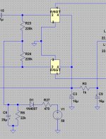
Hello, I'm trying to model a negative bias voltage supply circuit in LTSpice.
Nothing I try works.
Is this something can be done?
All of my components are copied from the original schematic.
The bias tap on my PT is 50V. I need about -27V on the grids.
Thanks for any help!
Nothing I try works.
Is this something can be done?
All of my components are copied from the original schematic.
The bias tap on my PT is 50V. I need about -27V on the grids.
Thanks for any help!
Attachments
- Home
- Amplifiers
- Tubes / Valves
- Vacuum Tube SPICE Models