Hi,
I am planning a new project, from the RC-29 RCA 1973 tube handbook:
"High-Fidelity Audio Amplifier 50 Watts".
I intend to follow the schematic as close as possible.
For now, I have collected most parts and I am designing the chassis.
Any comments are welcome!
I am planning a new project, from the RC-29 RCA 1973 tube handbook:
"High-Fidelity Audio Amplifier 50 Watts".
I intend to follow the schematic as close as possible.
For now, I have collected most parts and I am designing the chassis.
Any comments are welcome!
Attachments
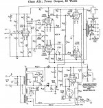
Hi, looks a bit complicated to me, as power valves screen grids are fed by a cathode follower made with a 6GF7, and this tube is heated by another power trafo secondary. Also, how to calculate open- and closed-loop gains, if no resistor values are shown, and to assure frequency response of output trafo being same as of the the ones used in '73?
Hi Grasso,
all component values are shown in the RCA tube manual parts list.
Years ago, the power transformer was custom made for me by A.E. in Holland.
For stereo, it is a big one!
The seperate heater supply is for the 6GF7 only, that is the stabilized power supply for the screen grids of the output tubes.
Output transformers are from Hammond, 100W types.
All comments and suggestions are welcome!
Best regards, 968driver.
First, it builds on a extinct tube : 7199, the other are rare too.I am planning a new project, from the RC-29 RCA 1973 tube handbook:
"High-Fidelity Audio Amplifier 50 Watts".
Second: it's complicated and needs adjustment of balance control.
I would suggest something simular to dynaco Mk-III using 6550 and
the rare but obtainable 6an8 .
third: the separate screensupply could be scrapped and replaced by
a resistive network ( unless UL connection is used instead)
Do all these things and it's no longer the amplifier described or desired by the OP. None of the tubes are that hard to source, and worst case the 7199 can be replaced with 6BL8, 6AN8 or 6U8A.
I would ditch the 7199 and I would consider bandersnatch's advice as well, but only once the amplifier is actually working correctly.
Regulated screen grids are a significant performance enhancement and one of the attractions of this design.
I would ditch the 7199 and I would consider bandersnatch's advice as well, but only once the amplifier is actually working correctly.
Regulated screen grids are a significant performance enhancement and one of the attractions of this design.
Yes, i found that design interesting too.
A problem is the high sensitivity for the today sources, something of ¼volts.Also the tubes are not to easy to find.
Sometime ago i cooked another version together, only on "paper" (can't build anymore).
More simple, no stabilised g2 but UL and one tube (findable Ask Jan) less with an input a little over 1volts.
Mona
Attachments
One could suggest all manner of different circuits, it depends on what's desired.
Remaining close to the original, oine must remember that this circuit appeared in the 60's. UL was barely known then, as was not other alternatives.
I would support regulation for the 7027 screens, particularly wiith beam power tubes. (Beam tubes encounter a rather large variation in screen current during operation; 50W might not be reached with an unregulated supply.) For this one could use s.s. regultors - s.s. power supplies do not take part in the signal line and thus using semoconductors there do not make it any less of a tube amplifier!
But to slight modernising then: I would advise the use of the UL topology. H.t. would just about fit in with the power tubes' maximum ratings (possibly a wee bit more bias). For the rest, as advised above by other members.
Last edited:
If one already has 100 Watt OTs, and also using a regulated screen V, might as well sub in some cheap TV Sweep tubes to get the full 100 Watt output ( need to drop the reg. screen V to 150V or so and increase B+ some for 100 Watts).
"50 tube Watts is a lot of power. What will you drive? "
Bigger tubes just look better, even for just 5 Watts out. Get some 26/36LW6 tubes.
"50 tube Watts is a lot of power. What will you drive? "
Bigger tubes just look better, even for just 5 Watts out. Get some 26/36LW6 tubes.
Attachments
Last edited:
Thanks for all comments!
As I said earlier, I want to stick to this 1973 RCA schematic, as close as possible.
Since it was published in one of RCA's last vacuum tube manuals, I think it represents the state of the art of the seventies. (This is not a sixties design).
For the moment, I have some confidence in the RCA engineers of yesterday.
If the circuit does not perform well, I will modify it, but only if necessary.
As for the tubes, I have collected all these tubes some time ago, and you still can find them.
My speakers are Klipsch Cornwall III.
As for now, I drive them with a 10 W triode tube amplifier, with very good results.
The RCA amplifier is totally different and I am curious how it will sound with the Corwall speakers.
The pure visual aspect of 14 glowing tubes will also be something special!
I hope to have this project ready somewhere after summer.
All comments are welcome!
Best regards, 968driver.
You might get disappointed with it: just because someone titled the schematics "50 Wa Hi-Fi" - it's the last winter's snow ))
As others pointed out the UL will likely give better results.
The Cornwalls are not in my dream-list, but for those I would not bother with 50 Wa, half of that is plenty. Instead, I d build an amp with best possible damping factor, and certainly with custom-ordered oversized OPTs, some cool stuff like Pi windings:
http://copyright.lenardaudio.com/laidesign/images/a14/a14_tranny-pi.jpg
Or, at least, get the best Japanese OPT you can afford.
Last edited:
Regulated screen grids are a significant performance enhancement and one of the attractions of this design.
No question there...I'd want to be able to adjust it just a wee bit so I could tune the tube operating conditions to the load. A slightly variable g2 supply is not to be despised. Pentode performance is at its maximum with *JUST* the right g2 voltage. Now that 'just right' depends on the requirements, and there are lots to choose from, many contradictory...
")
cheers,
Douglas
As I said earlier, I want to stick to this 1973 RCA schematic, as close as possible.
You can retain the topology, but the exact tubes will bankrupt you. 6L6GC "finals" and 6BL8 pentode-triodes (as has already been suggested) are very reasonable substitutes.
RCA's bias supply using a dropping resistor of 1 end of the HT winding is "Cheap Charlie".
 If the custom power trafo does not have a bias tap or separate bias winding, purchase a low cost toroid. If the toroid is acquired, bridge rectify with 4X Schottky diodes.
Don't let anyone nay/say full pentode mode "finals" with regulated g2 B+. That's a superb method for minimizing open loop distortion.
Don't let anyone nay/say full pentode mode "finals" with regulated g2 B+. That's a superb method for minimizing open loop distortion.
This one also dispenses with the traditional complaint of high plate resistance with a bit of Schade, plate-to-grid.
http://www.diyaudio.com/forums/tubes-valves/271134-schade-cfb-exactly-equivalent.html
cheers,
Douglas
Hi,
I am planning a new project, from the RC-29 RCA 1973 tube handbook:
"High-Fidelity Audio Amplifier 50 Watts".
I intend to follow the schematic as close as possible.
For now, I have collected most parts and I am designing the chassis.
Any comments are welcome!
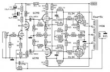
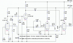
It resembles my Pyramid design; just different tubes, and different signal levels per stages. Also, I use solid state rectifiers and voltage regulators. ;-)
Also, I have 3 directly coupled stages, and a servo from the tail of LTP to the screen grid of the 1'St pentode to keep them all together.
Yes, i found that design interesting too.
A problem is the high sensitivity for the today sources, something of ¼volts.Also the tubes are not to easy to find.
Sometime ago i cooked another version together, only on "paper" (can't build anymore).
More simple, no stabilised g2 but UL and one tube (findable Ask Jan) less with an input a little over 1volts.
Mona
I love nested feedbacks myself! It is a 21'St Century design!

Last edited:
Do all these things and it's no longer the amplifier described or desired by the OP. None of the tubes are that hard to source, and worst case the 7199 can be replaced with 6BL8, 6AN8 or 6U8A.
I use 6F12P. And 6P15P in a driver LTP.
Attachments
- Status
- This old topic is closed. If you want to reopen this topic, contact a moderator using the "Report Post" button.
- Home
- Amplifiers
- Tubes / Valves
- vacuum tube power amplifier 2 x 50 W