IRF 820 isnt a bad alternative, reasonably low capacitance 350 odd pF as I recall, and 2.5A and 500V, 50W p diss....
IRF 830 Ive used in the past but the gate-capacitance is higher at 600 odd pF, --Works OK though....
Basically any 'N' channel MOSFET with a high enough voltage-rating for the circuit, (So above 350V) and a low gate-capacitance will be fine...
IRF 830 Ive used in the past but the gate-capacitance is higher at 600 odd pF, --Works OK though....
Basically any 'N' channel MOSFET with a high enough voltage-rating for the circuit, (So above 350V) and a low gate-capacitance will be fine...
B+ relay fitted.
Switched from selector switch.
Just for interest I didn't want to use a neon for the supply indication: 240v AC. I remembered a circuit using a capacitor to replace the resistor for an LED. This is close I think, I haven't had chance to test and check it yet . Looks close though! Cap might be .22uF for 240V....Toroid has no low voltage out..
Link:
http://www.turbokeu.com/myprojects/acled.htm
Should also work with opto-isolaters.
I got my IRF710's from Farnell.
Regards
M. Gregg
Alastair,
I have used individual fuses for the B+/B- on each set of valves. (one in the anode of U3 and one in the cathode of U4).
I know the fusing is important for maximum protection.
I have a 1.5 T on the speaker out.
Any thoughts on fusing for each tube.
We are setting tube idle at 200mA I believe?
So are we looking at 1.5A per tube Time lag or quick blow in each tube supply?
Still some work to do, I should be checking the bias soon.
I will start with 300 Ohm per tube cathode and see what I get.
Regards
M. Gregg
Last edited:
Running 150V +- rails on O/P stages I'm using 220 ohm and get approx 180mA....
Seems a fair assumption that yours should be reasonably close to the same--even though your tubes are brand-new, and mine have several hundred (Maybe even over a thousand!) hours on them....
I really should buy some new ones when I can afford them.....!
As to fusing, I have a 1.5A A/S on the speaker-output and 1.5A A/S on each of the two supplies to each channel--each channel has its own + rail fuse and - rail fuse....
Not had any blow, so should be OK....
Last edited:
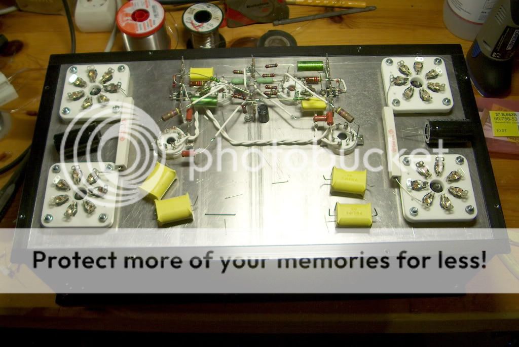
Hey! Coming along well!
That layout on the first stage isnt unlike mine, the MOSFET mounted direct to the chassis via insulating-pad.
Works well, it doesnt make much heat, just a couple of watts so doesnt need a dedicated heatsink....
When you come to wire up the 6C33 heaters, make sure you use as thick wire as possible to easily solder to the socket-pins...
--Not for the current, but more for the heat-sinking effect the thick wire will give....
I used some rubber-covered wire I got from an industrial Elect Motor re-winder,--They use it for the tails into the connecting-box from the coil-windings....
No issues or degrading yet, even close at the soldered joints....
I guess so....Coil-winding wire you mean...?
But, its difficult to work with being single-cored thick wire and the insulation is only the enamel coating....
The stuff I used is multi-core so is easily made into twisted pairs and easily dressed where you want it. The insulation puts up with the heat well, as motors can often run very hot, its made to withstand that....")
But, its difficult to work with being single-cored thick wire and the insulation is only the enamel coating....
The stuff I used is multi-core so is easily made into twisted pairs and easily dressed where you want it. The insulation puts up with the heat well, as motors can often run very hot, its made to withstand that....
I have run the power section on its own without pre /driver stage connected.
Yep the tubes get hot!
I am getting about 140mA across the 300 Ohm resistors. App 42V - 43V.
They smell a bit while burning in..
I am glad that I fitted the B+ switching. If I want to go and make a coffee I can put it in standby. With the 2 different heater configs and the choice of B+ on or off it gives a lot of flexibility.
I might try the 140mA setting and see if I need any more power.
I will connect the pre/driver next. Offset (quick check) no changing tubes arround is 21mV.
Regards
M. Gregg
With my experience I think you will need a shoe horn...LOL
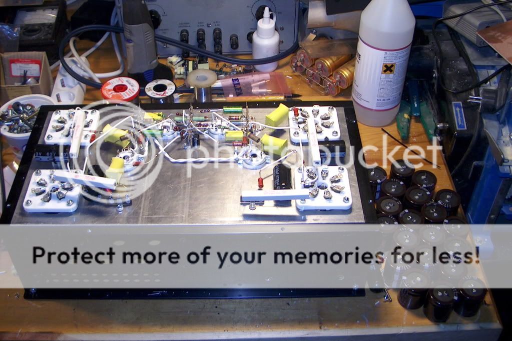
I found I just kept adding more and more components .....Space seems to get tight very quickly..
I am glad I put my capacitors behind a heat shield!
I would try and keep them away from the sockets if you can.
Regards
M. Gregg
I found I just kept adding more and more components .....Space seems to get tight very quickly..
I am glad I put my capacitors behind a heat shield!
I would try and keep them away from the sockets if you can.
Regards
M. Gregg
Last edited:
I found the links in this thread very helpful!
6C33C spacing
I would build standard and try the amp, modify with electronic chokes if you need to!
I am just hoping all goes well at final power up...LOL
Regards
M. Gregg
6C33C spacing
I would build standard and try the amp, modify with electronic chokes if you need to!
I am just hoping all goes well at final power up...LOL
Regards
M. Gregg
Last edited:
- Status
- This old topic is closed. If you want to reopen this topic, contact a moderator using the "Report Post" button.
- Home
- Amplifiers
- Tubes / Valves
- Vacuum Tube OTL power amp!!