Alastair,
Quick question:
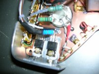
Pin 5# on the 6c33c tubes - Grid stopper resistor.
The normal practice would be to mount as close to the tube pin as possible.
Taking heat into account how have you mounted the resistors?
Direct onto the tube socket pin (close) or (via wire) or (using full length of resistor leg to tube base?)
Regards
M. Gregg
Quick question:
Pin 5# on the 6c33c tubes - Grid stopper resistor.
The normal practice would be to mount as close to the tube pin as possible.
Taking heat into account how have you mounted the resistors?
Direct onto the tube socket pin (close) or (via wire) or (using full length of resistor leg to tube base?)
Regards
M. Gregg
Thank's Alastair,
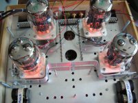
I completed the heater wiring and can switch in (outside front-inside rear)-(inside front- outside rear)-all.
I wanted to test the heat aspect with just heaters. All seems OK. The sockets do get quite warm with just heaters and I expect this to increase with conduction B+ on. The heat shield I put in makes a big difference between one side of it and the other. I still have to complete more wiring on the B+ fusing etc with the 6c33c's. I will leave them on for now just to burn in the tubes.
These are only my thoughts, I would guess that with a chimney effect through the chassis the air movement would be greater than tubes in free air! (cooling better maybe!)
I made up the heater cables with small size PTFE and twisted into a multi strand cable. Just to see what happens. current should be in the 30A range only using about (current in series 24V is way down < 3A). Tends to look like a 1960's computer main frame..LOL (Overkill)
I guess this is irrelevant until I see if there is any interaction when B+ is on!
Still more to do.
Regards
M. Gregg
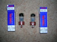
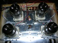
Arrived today,
Also gate stopper moved.
Heaters on etc.
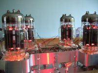
Just for fun photos.
Heaters have been on for 9 hours so far!
Regards
M. Gregg
Also gate stopper moved.
Heaters on etc.
Just for fun photos.
Heaters have been on for 9 hours so far!
Regards
M. Gregg
Attachments
Last edited:
I have about 120V on the anode, and a little less on the grid of the phase-splitter...
Sounds like you're nearly there!
Alastair,
Just for interest I have run the pre/driver board.
Voltages on 6SL7 pin 5#.......215 - 223 (Anode) L/R
Voltage on pin 1# and pin 4# of 6Sn7 .......205 - 210V (Grid)
Regards Grid to Cathode protection Neons.
They come on for about 5 seconds and then turn off.
So yes at start up we have at least 40V or more between the grid/cathode when the heaters are warming up. So this seems to work!
No signal has been applied yet.
The DC heaters work for the 6SL7's, again no signal to see if they interact.
What voltage do you have on pin 2# 6SL7 Anode? (1st stage after input)
I have 174.4V / 174.2V L/R....pin2# Anode.
B+ is 355.9V
Regards
M. Gregg
Last edited:
Hmmm....
Summit a bit odd there.....
Anode of my 6SL7 is around 130V, and as this is coupled to the phase-splitter, determines the op/point of the phase-splitter, to give more or less equal volts across the two splitter resistors and the tube itself, so this sorta needs to be right...
What voltage do you have on the 3/1 voltage-divider to the high-value resistor into MOSFET gate of the 'mu-follower' above the 6SL7....?
My H.T is a little lower at 350V, but yours at 355 is fine. I suspect maybe the voltage at the gate of MOSFET is wrong--Perhaps you got the resistors wrong-way round, ie--the 3/1 divider resistors,--not end to end!....")
IF thats all correct, maybe there's some oscillation going on....
Summit a bit odd there.....
Anode of my 6SL7 is around 130V, and as this is coupled to the phase-splitter, determines the op/point of the phase-splitter, to give more or less equal volts across the two splitter resistors and the tube itself, so this sorta needs to be right...
What voltage do you have on the 3/1 voltage-divider to the high-value resistor into MOSFET gate of the 'mu-follower' above the 6SL7....?
My H.T is a little lower at 350V, but yours at 355 is fine. I suspect maybe the voltage at the gate of MOSFET is wrong--Perhaps you got the resistors wrong-way round, ie--the 3/1 divider resistors,--not end to end!....
IF thats all correct, maybe there's some oscillation going on....
Last edited:
Alastair,
Are the voltages on the phase splitter correct?
Post 190#
Anode pin2#......209V.......cathode pin3#....141V
Anode pin5#.......210........cathode pin6#.....140.9V
Votages to Gnd
B+ 355v -209 =146 across top resistor and 141v on cathode resistor.
Regards
M. Gregg
Are the voltages on the phase splitter correct?
Post 190#
Anode pin2#......209V.......cathode pin3#....141V
Anode pin5#.......210........cathode pin6#.....140.9V
Votages to Gnd
B+ 355v -209 =146 across top resistor and 141v on cathode resistor.
Regards
M. Gregg
Last edited:
Alastair,
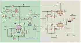
Here is the schematic with voltages attached..I haven't changed the tube pin outs.
I guess changing the top 100K (R12) to 200k would move the position if the first triode anode voltage.
Phase splitter may be OK as is?
Regards
M. Gregg
Here is the schematic with voltages attached..I haven't changed the tube pin outs.
I guess changing the top 100K (R12) to 200k would move the position if the first triode anode voltage.
Phase splitter may be OK as is?
Regards
M. Gregg
Attachments
Last edited:
Ah--Right, NOW I see whats what!
That scheme you have there, is set up for 6SN7 not a 6SL7 for the first two stages and SN7 for the phase-splitter...
For 6SL7, you'll need to change the R10 to 100K, and R3 to around 1K.
The 4.7K R1 in the MOSFET tail can be increased to around 10K and the cathode-resistor to 800-1.2K
---What you Could do is just use the SN instead of SL if you have one round--which would be the best way forward, Not sure the second stage will have the voltage-swing needed without clipping if SL is used there...
The 100K's we talked about earlier in this case, should be as you had/have them, 100K each...
Ah,
So if I use 6sn7 for all three tubes the bias should be correct?
I assumed we were going with 6sl7 first tube and sn7 for the splitter.
So the bias on the FET is correct.
Any idea what should the voltages be on the phase splitter?
I will just go with all sn7 if that is the way forward.
Sorry its probably info overload from me..
Regards
M. Gregg
Yes, In the post 133, it actually is marked, 6SN7 for the first tube, and 6J5 (Half a 6SN7) as phase-splitter.
All bias etc should be good with the 6SN7 as first tube and phase-splitter.
There should be around equal volts across each of the phase-split resistors and more or less the same across the tube.
All bias etc should be good with the 6SN7 as first tube and phase-splitter.
There should be around equal volts across each of the phase-split resistors and more or less the same across the tube.
Thank's Alastair,
I think its because we changed over half way through. Different circuits!
For some reason SL got stuck in my mind..LOL
Anyway as it stands its DC heaters for the input tubes and AC for the phase splitter. All 6SN7.
I hope to make some more progress over the next few days.
Just wiring the 6c33c's.
The 6c33c's have been run heaters on for 12Hrs so hopfully they will be OK.
Regards
M. Gregg
Last edited:
Yup--Sounds like yours nearly ready to run....
There was a little confusion fairly early on in the thread regarding the SL/SN tube issue, as this thing has gone through more versions than a Ford Transit...
Fairly settled now on the above scheme though!
Ive done some experimenting with cathode-follower drive to the 6C33 but no real benefit for 'normal' listening, just makes the O/P slightly higher before obvious clipping,--Not really worth the effort, and adding another valve per channel.
--Still to try driving the 6C33 with MOSFET followers for a larf, --just to see what difference there is...
Guess for +B switching, you could just have a switch that cuts the power to the large toroid that only supplies the 6C33 +/-B rails....
The pre-amp sections are not so important with regards that so can be left as normal.
I dont have a 'Standby' function--Never have, Its full +/-B from stone-cold!
--65 million TV sets can't be wrong!
The pre-amp sections are not so important with regards that so can be left as normal.
I dont have a 'Standby' function--Never have, Its full +/-B from stone-cold!
--65 million TV sets can't be wrong!
- Status
- This old topic is closed. If you want to reopen this topic, contact a moderator using the "Report Post" button.
- Home
- Amplifiers
- Tubes / Valves
- Vacuum Tube OTL power amp!!